Gen5 应用实例

系列文章目录
博通PCIe 5.0 Switch学习笔记(2)—— 应用实例
文章目录
- 系列文章目录
- 一、Fanout switch
- 二、Graphics Processing Unit
- 三、NvMe Hot Add and Hot Remove
- 四、高可用性存储用例
- 五、冗余存储
- 六、多域通用 GPU
- PCIe switch Fabric
- 简单树形拓扑 (Simple Tree Topology)
- 双树拓扑 (Dual Tree Topology)
- 网状拓扑 (Mesh Topology)
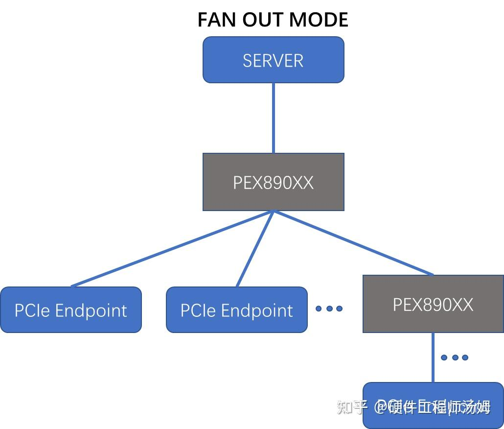
一、Fanout switch
在数字电路中,“扇出”(Fan-Out)指一个逻辑门的输出能够有效驱动的其他逻辑门或负载的数量。若某个开关被称为“FANOUT switch”,可能是指一种用于控制信号分配的开关,将单个输入信号分发到多个输出端。
二、Graphics Processing Unit
图形应用程序通常使用 x16 宽度的链路。交换机硬件支持点对点通信,从而允许对等体之间使用尽可能短的路径。与扇出交换机一样,链路可以支持任何支持的 PCle 速度和宽度。
Graphics applications typically use x16-width links. Peer-to-peer communication is supported in switch hardware, allowing the shortest possible path between the peers. As with the fanout switch, the links can be at any supported PCle speed, for any supported width.
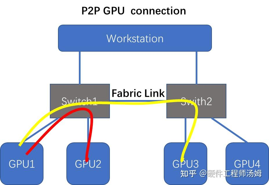
- GPU1 可以通过交换机 Switch 1 与 GPU2 通信。
- GPU 1 可以通过交换机 Switch 1 与交换机 Switch 2 之间的结构链路与 GPU3 通信。
注意:P2P 需要软件支持。
GPU1 can communicate with GPU2 using switch Switch1.
GPU1 can communicate with GPU3 using switch1 through a fabric link to switch2.
注意:P2P Requires software support.
三、NvMe Hot Add and Hot Remove
此交换机支持将 PCle 设备添加到服务器或主机中空插槽的系统,而不会中断 PCle 树的其余部分。
This switch supports a system that can add a PCle device to an empty slot either in a server or in the host without disrupting the rest of the PCle tree.
-
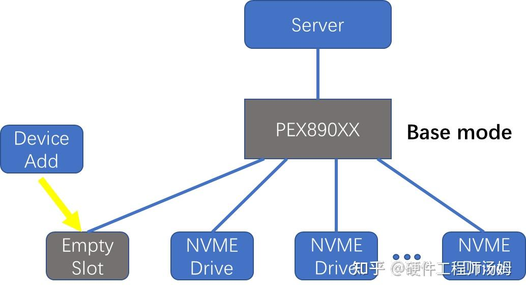
Base Switch Mode
在基础交换机模式 (base switch mode, BSw) 下,系统软件必须在主机启动时为空插槽预分配资源。In base switch mode (BSw), system software must preallocate resources for empty slots at host boot time.
参看下图:
-
Synthetic Switch Mode
难点在于如何在配置时预留 PCle 资源,以便稍后添加设备。功能上,合成交换机 (sSw) 模式使用管理软件创建占位端点来预留 PCle 资源。The challenge is to reserve PCle resources at configuration so that you can add devices later. Functionally, synthetic switch (sSw) mode uses management software to create a placeholder endpoint to reserve PCle resources.
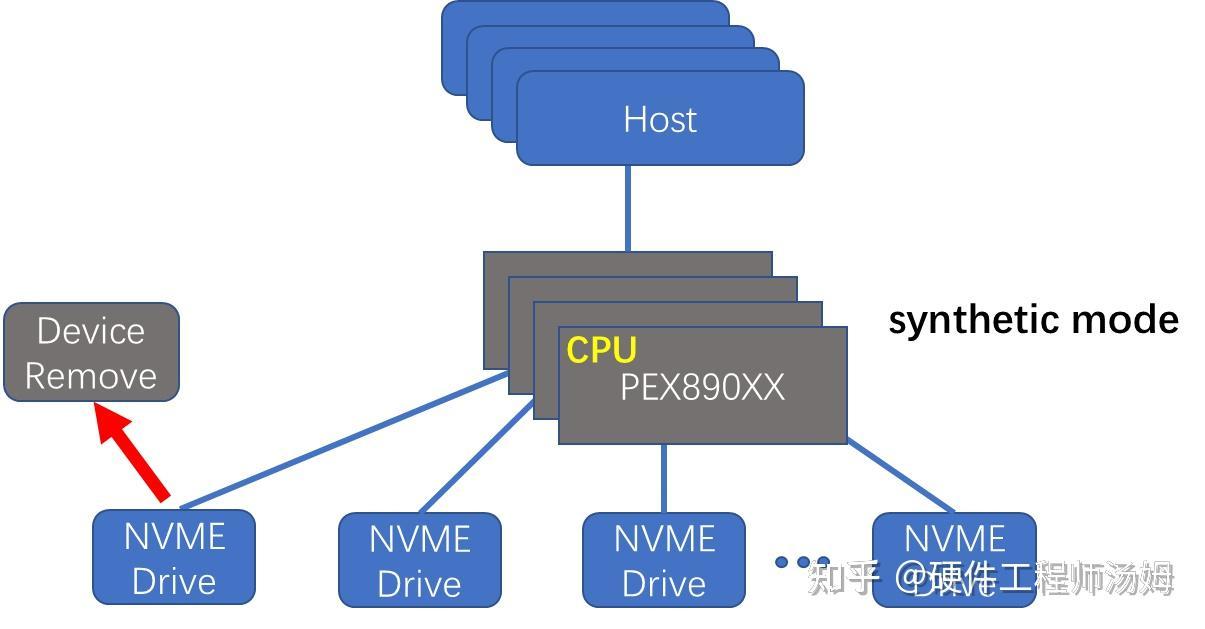
有关模式信息,请参阅操作模式。您可以随时从服务器或主机移除设备,而不会中断其他端口。使用 DPC 可防止端点错误蔓延到树的其余部分。启用读取跟踪可防止完成超时。
See Operation Modes for mode information. You can remove devices from either the server or the host at any time without disrupting other ports. Use DPC to keep endpoint errors from spreading to the rest of the tree. Enable read tracking to prevent completion timeouts.
四、高可用性存储用例
High Availability Storage Use Case
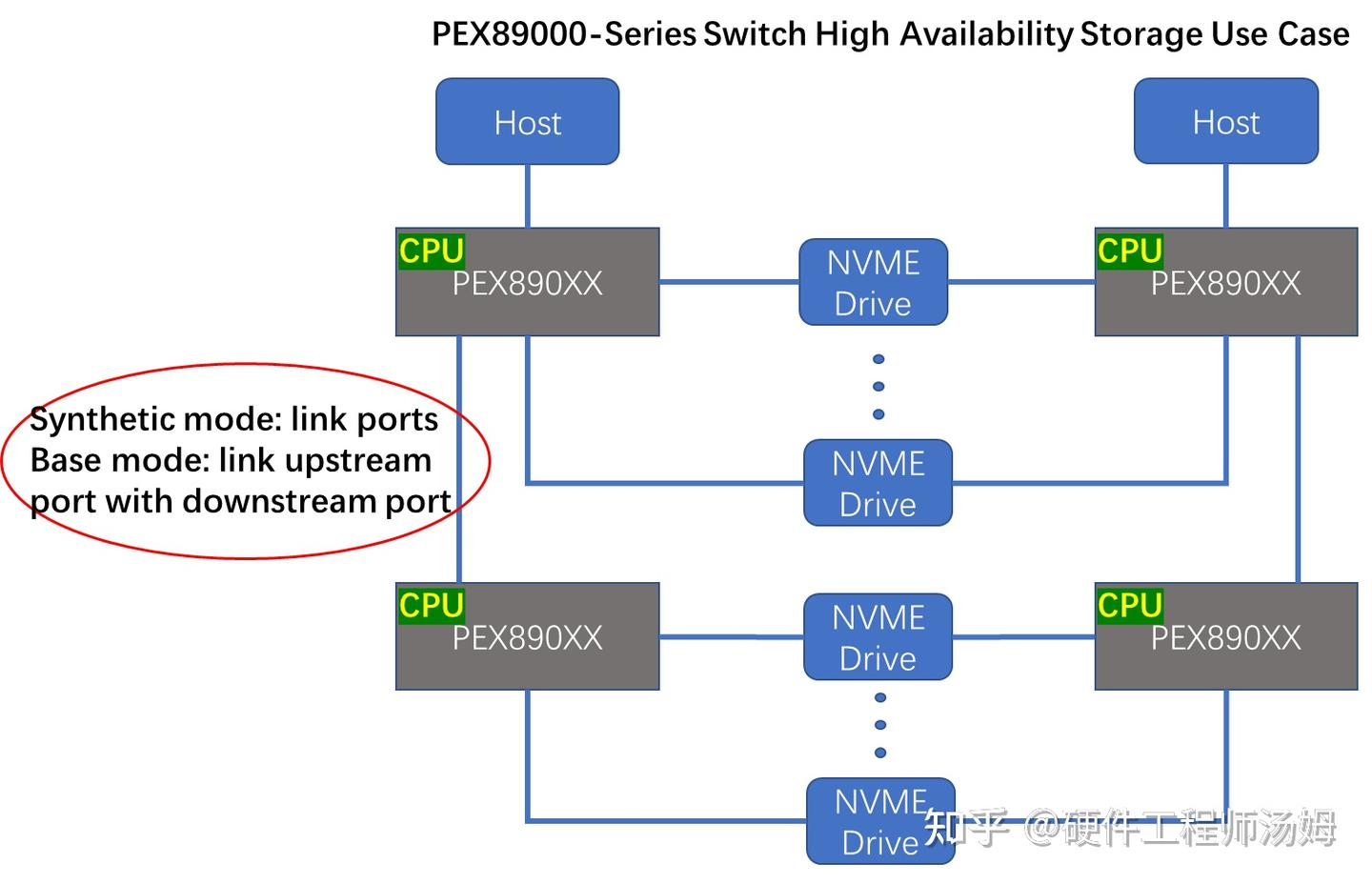
交换机与双端口 NVMe 驱动器配合使用,提供高可用性存储,即消除单点故障。以下拓扑通过冗余实现高可用性存储——每个 NVMe 设备都有两条路径。两台主机各自拥有独立的交换机层级结构。
The switch works with dual-ported NVMe drives to provide high availability storage, that is, no single point of failure. The topology that follows achieves high availability storage through redundancy-two paths to each NvMe device. Each of the two hosts has its own independent switch hierarchy.
-
如果交换机处于 isSw 模式,则交换机之间的链路连接两个合成交换机端口。
-
如果交换机处于 BSw 模式,则交换机之间的链路连接下游端口和上游端口。
If the switches are in isSw mode, the link between switches connects two synthetic switch ports.
If the switches are in BSw mode, the link between switches connects a downstream port to an upstream port.
上图解决了以下可能发生的故障:
- 如果一台主机发生故障,另一台主机仍然可以访问每个 NVMe 驱动器。
- 如果交换机发生故障,则存在一条备用路径来访问端点上的数据。
- 如果任何链路发生故障,上游侧会认为下游侧已发生故障。
- 如果到交换机上游端口的链路发生故障,则该交换机在主机上显示为故障。
- 如果到 NvMe 驱动器的链路发生故障,则该端点在使用该路径的主机上显示为故障。
- 如果端点(上图中的 NvMe 驱动器)发生故障,则该驱动器上的数据将不再可访问。
在此示例中,上游交换机(左侧和右侧)应为合成交换机,以支持最强大的 NvMe 意外设备添加或移除功能。
In the preceding figure, the possible failures that follow are addressed:
- If one host fails, the other host can still get to every NVMe drive.
- If a switch fails, an alternate path exists to access the data on the endpoint.
- If any link fails, the upstream side considers the downstream side to have failed.
- If the link to an upstream port of a switch fails, the switch appears as failed to the host.
- If the link to an NvMe drive fails, the endpoint appears as failed to the host that uses that path.
- If an endpoint (an NvMe drive in the preceding figure) fails, the data on that drive is no longer accessible.
In this example, the upstream switches (both left and right sides) should be synthetic switches to support the most robust NvMe surprise device add or remove.
五、冗余存储
Redundant Storage
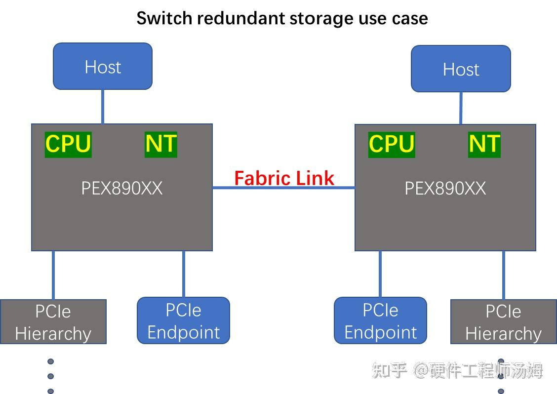
上一代镜像系统可能具有相同的主板,并通过交联链路连接背对背非透明 (NT) 桥接器。PEX89104 交换机型号用光纤链路取代了 NT-NT 链路。在所有此类镜像系统中,每台主机都会找到一个 NT 端点,通过该端点与另一台主机通信。
光纤链路在两台主机系统之间提供(主机隐藏的)数据路径。当一台主机发生故障时,另一台主机可以接管第一台交换机的端点。
在此用例中,交换机必须处于合成模式才能启用 NT 端点。光纤链路连接两台交换机。每台交换机都应配置一个合成交换机端口以连接到光纤链路。
Previous generation mirrored systems might have identical boards connected with back-to-back non-transparent (NT) bridges connected through a crosslink. The PEX89104 switch model replaces the NT-NT link with a fabric link. In all such mirrored systems, each host finds a single NT endpoint through which it communicates to the other host.
The fabric link provides a (hidden-to-host) data path between the two host systems. When one host fails, the other host can take over the endpoints of the first switch.
In this use case, the switch must be in synthetic mode to enable the NT endpoint. A fabric link connects the two switches. Each switch should configure a synthetic switch port to connect to the fabric link.
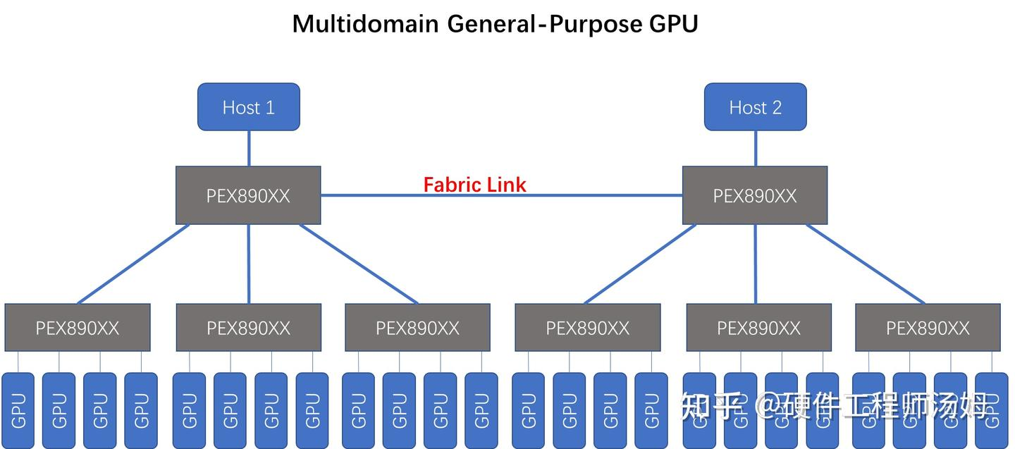
六、多域通用 GPU
Multidomain General-Purpose GPU
该交换机支持域内和域间的通用 GPU (GPGPU) 对等事务。在以下示例中,交换机处于 iSSw 模式,通过 Fabric 链路连接。
The switch supports general-purpose GPU (GPGPU) peer-to-peer transactions within a domain and between domains. In the example that follows, the switches are in iSSw mode, connected by a fabric link.
PCIe switch Fabric
关于PCIe switch Fabric top的笔记:
标准 PCIe 树形拓扑结构存在一些限制。在 SSw 模式下,交换机支持替代拓扑结构来解决这些限制。SSw 模式下,两个 PCIe 交换机之间的链路可以连接两个交换矩阵端口,所有 TLP 都通过目标 ID 路由到这两个端口。这种方法允许任何一个源使用可编程交换矩阵路径到达任何一个目标。
全局 ID (GID) 用于跨交换矩阵路由 TLP。如果存在多条可用路径,目标 GID 会索引目标查找表 (D-LUT) 以获取选择向量。根据选择向量,系统会选择特定的交换矩阵端口。
全局 ID 的构成:GID 由 {domain[7:0],ID[15:0]} 组成,其中 ID 值是一个 PCIe 标准 ID,由 {bus[7:0], device[5:0], 和 function[2:0]} 组成。
管理软件在硬件中设置地址陷阱、ID 陷阱或两者兼而有之,以接收普通 PCIe TLP 并创建目标 GID。管理软件还会对 D-LUT 中的路由表和选择映射寄存器进行编程。
注意:Fabric 拓扑需要固件支持。
The standard PCIe tree topology has some limitations. In SSw mode, the switch supports alternate topologies to address those limitations. The link between two PCIe switches in SSw mode can connect two fabric ports, upon which all TLPs are routed with a destination ID. This approach allows for any one source to get to any one destination using a programmable fabric path.
A global ID (GID) routes a TLP across a fabric. If there is more than one path available, the destination GID indexes a destination lookup table (D-LUT) to get a choice vector. From the choice vector, a particular fabric port choice is made.
Global ID构成:The GID is composed of {domain[7:0],ID[15:0]}, where the ID value is a PCIe standard ID composed of {bus[7:0], device[5:0], and function[2:0]}.
Management software sets up address traps, ID traps, or both in the hardware to take a normal PCIe TLP and create a destination GID. Management software also programs the route table in the D-LUT and the choice mapping registers.
NOTE Fabric topologies require firmware support.
该段落讨论了如何通过 iSSw 模式下的 switch 实现不同 topologies。它解释了如何使用GID路由TLPs,并且强调了firmware支持的重要性。
以下举例fabric port的应用:
简单树形拓扑 (Simple Tree Topology)
在以下 PCIe 树形拓扑示例中,根复合体在上游连接到 A0 PCIe 交换机上的主机端口。A0 PCIe 交换机通过结构 (f) 端口连接到 B0、B1 和 B2。下游 (d) 端口连接到标准 PCIe 设备(图中未显示)。标准 PCIe 设备可以是一个端点,也可以是一组连接到一组端点的交换机。
使用结构端口连接标准树中的交换机的一个好处是可扩展性。交换机使用的总线可以对主机隐藏,从而允许更多下游端点。
In the PCIe tree topology example that follows, the root complex connects on the upstream side to a host port on the A0 PCIe switch. The A0 PCIe switch connects through fabric (f) ports to B0, B1, and B2. Downstream (d) ports connect to standard PCIe devices (not shown in the figure). A standard PCIe device could be an endpoint or another set of switches that lead to a set of endpoints.
One benefit of using fabric ports to connect switches in a standard tree is scalability. The buses consumed by the switches can be hidden from the host allowing more downstream endpoints.

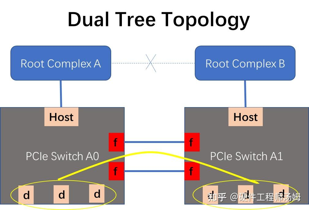
双树拓扑 (Dual Tree Topology)
一种常见的冗余拓扑结构是使用光纤链路连接两个相同的系统。在这种拓扑结构中,如果一台主机发生故障,另一台主机可以接管故障主机的端点。下图显示了交换机之间的两条光纤链路,用于添加另一个冗余点。
此外,光纤链路可以在对等端点(一个在 A0 上,一个在 A1 上)之间提供性能更高的路径(更高的吞吐量和更低的延迟),而不是在两个根联合体之间使用连接(图中虚线)。
A common topology for redundancy is to connect two identical systems with a fabric link. In this topology, if one host goes down, the other host can take over the failed host’s endpoints. The figure that follows shows two fabric links between the switches to add another point of redundancy.
Additionally, the fabric link could provide a higher performing path (more throughput and less latency) between peer endpoints, one on A0 and one on A1, instead of using a connection (the dashed line in the figure) between the two root complexes.
Dual Tree Example 如下图:
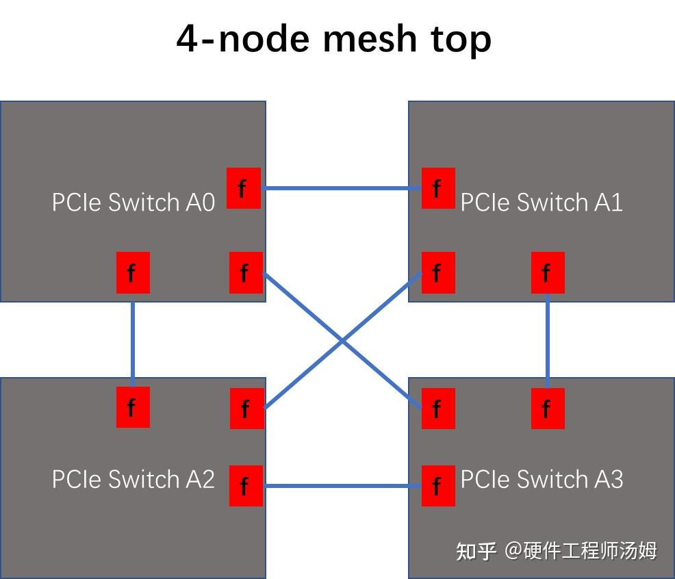
网状拓扑 (Mesh Topology)
网状拓扑将每个节点连接到其他所有节点。双树拓扑中所示的双交换机拓扑是一个 2 节点网状拓扑。PCIe 交换机最多支持 13 个节点的网状拓扑。下图显示的是一个 4 节点网状拓扑。
A mesh topology connects every node to every other node. The dual switch topology shown in Dual Tree Topology is a 2-node mesh. The PCIe switch supports up to a 13-node mesh. The figure that follows shows a 4-node mesh topology.