STM32F103按钮实验
目录
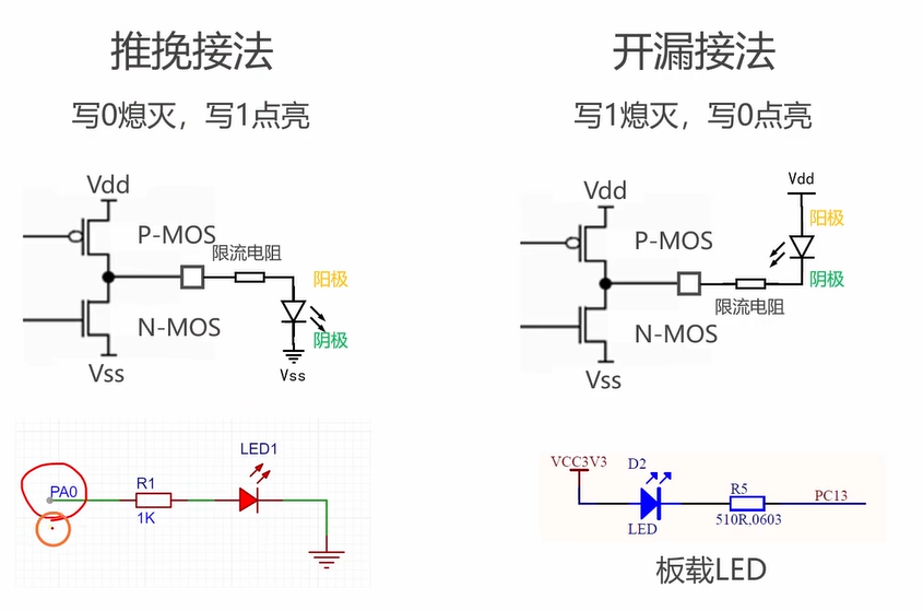
亮灯推挽输出
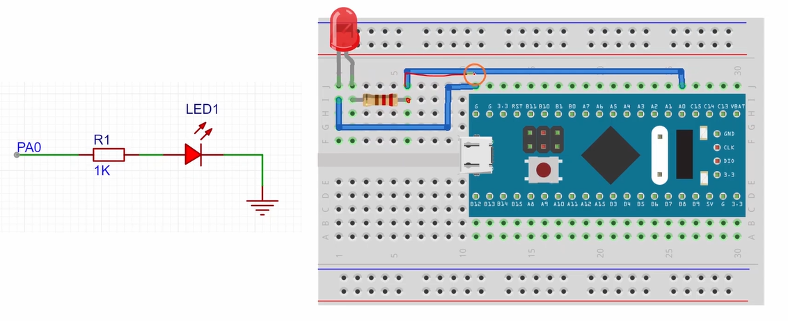
电路图
代码
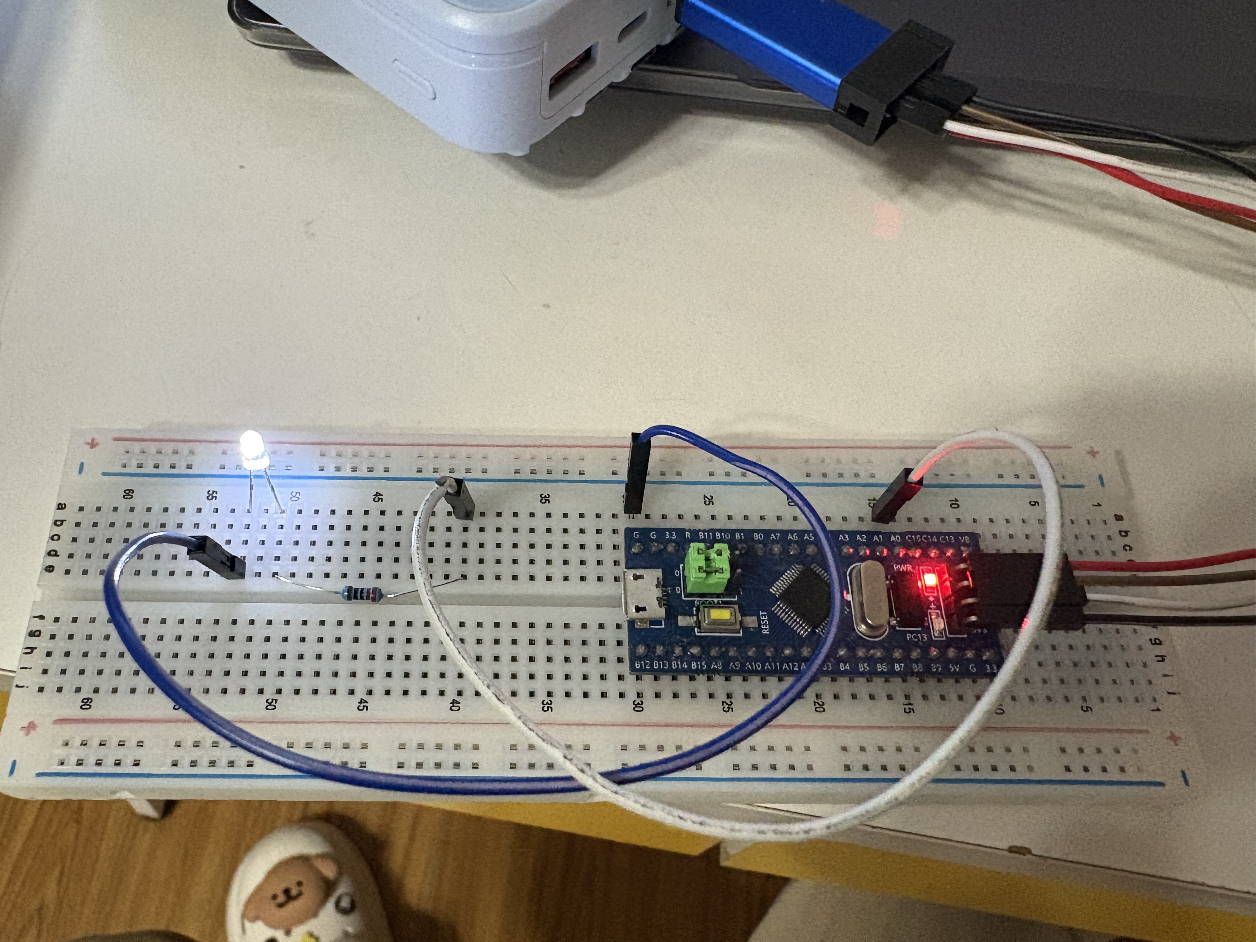
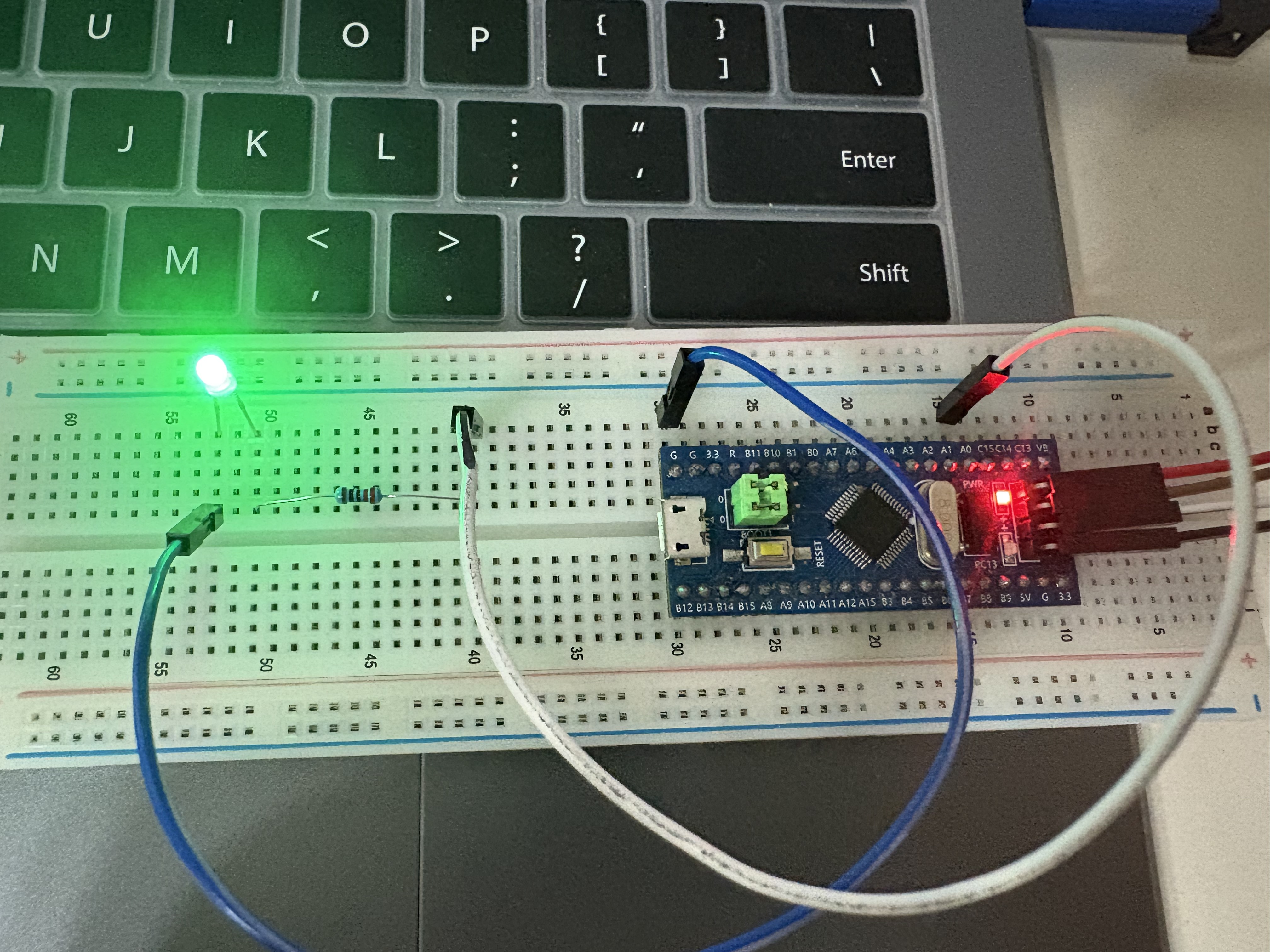
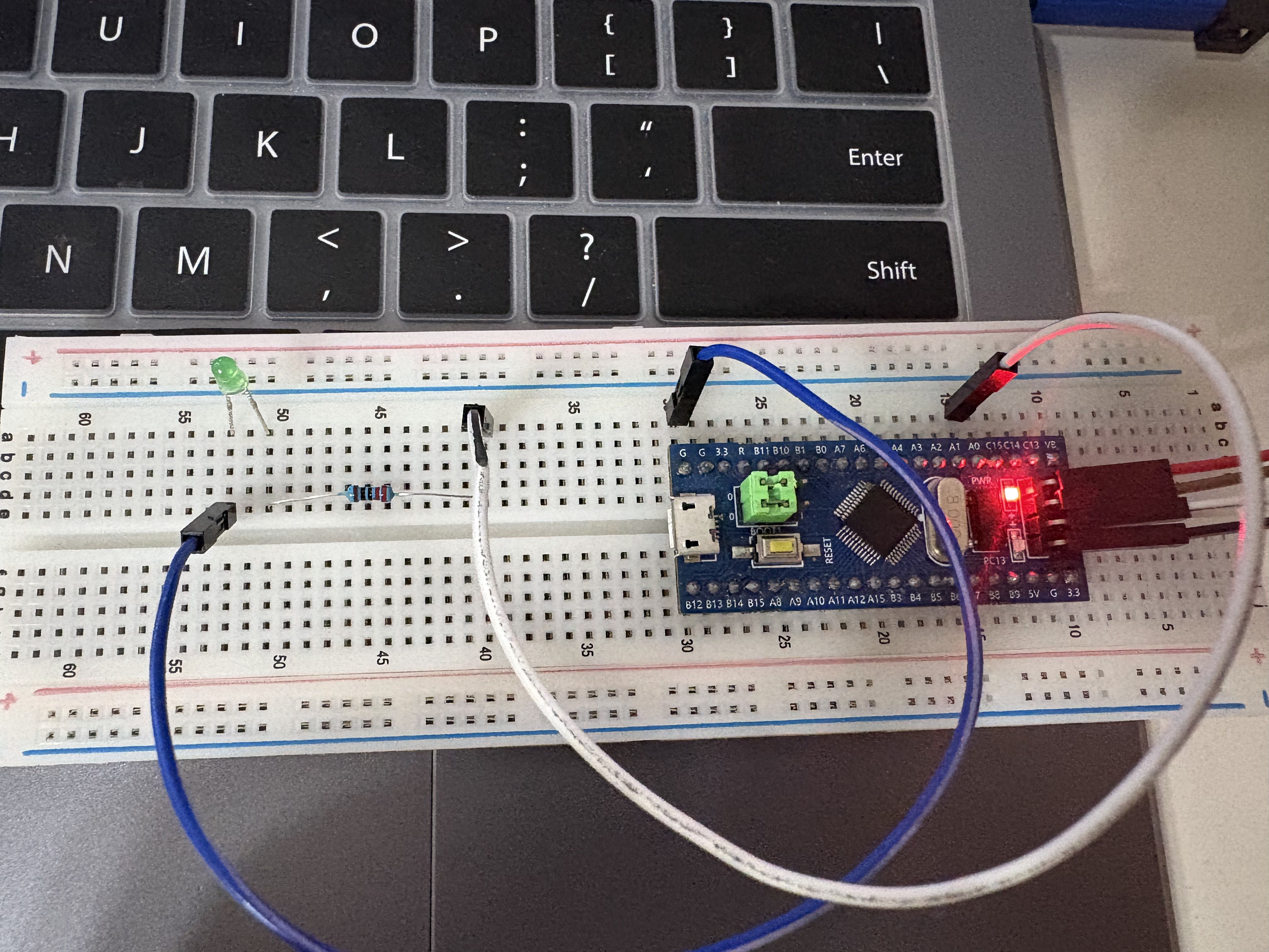
结果
按钮输入上拉模式
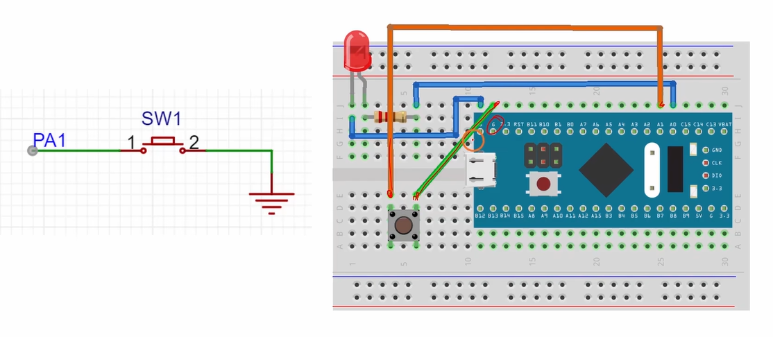
电路图
代码
亮灯推挽输出
电路图
代码
#include "stm32f10x.h"                  // Device header
#include "Delay.h"
int main(void)
{//开启时钟RCC_APB2PeriphClockCmd(RCC_APB2Periph_GPIOA,ENABLE);//定义结构体GPIO_InitTypeDef GPIO_InitStruct;GPIO_InitStruct.GPIO_Pin=GPIO_Pin_0;//推挽输出GPIO_InitStruct.GPIO_Mode=GPIO_Mode_Out_PP;GPIO_InitStruct.GPIO_Speed=GPIO_Speed_2MHz;//初始化GPIO_Init(GPIOA,&GPIO_InitStruct);while (1){//亮灯GPIO_WriteBit(GPIOA, GPIO_Pin_0, Bit_SET); Delay_ms(1000);//不亮灯GPIO_WriteBit(GPIOA, GPIO_Pin_0, Bit_RESET); Delay_ms(1000);}
}
结果
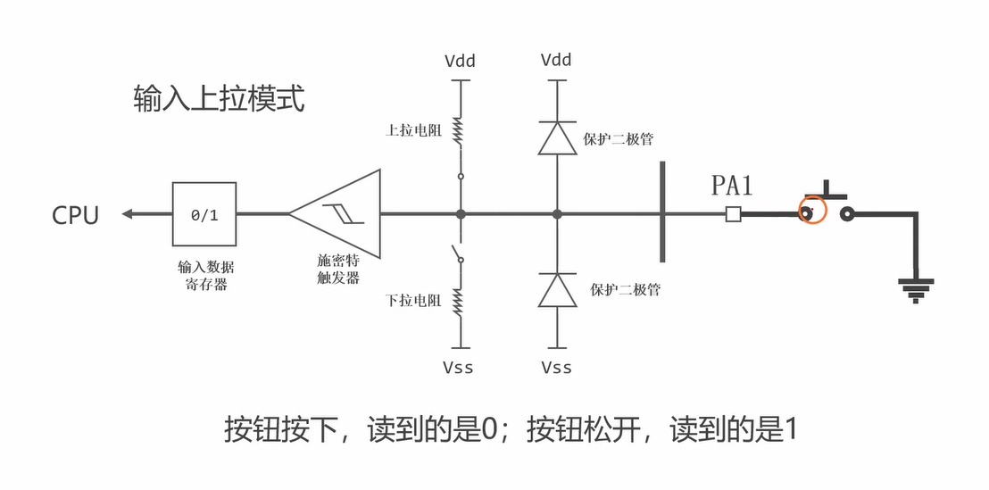
按钮输入上拉模式
当最右边按钮断开的时候,由于是输入上拉模式,上拉电阻闭合,Vdd导通,下面3.3V,施密特触发器将电压转为数字1,输入到数字寄存器
当最右边按钮闭合的时候,GND和施密特触发器导通,所以转为的为0输入到数字寄存器。
所以下面电路为
按钮按下,读到的是0。按钮松开,读到的是1。
电路图
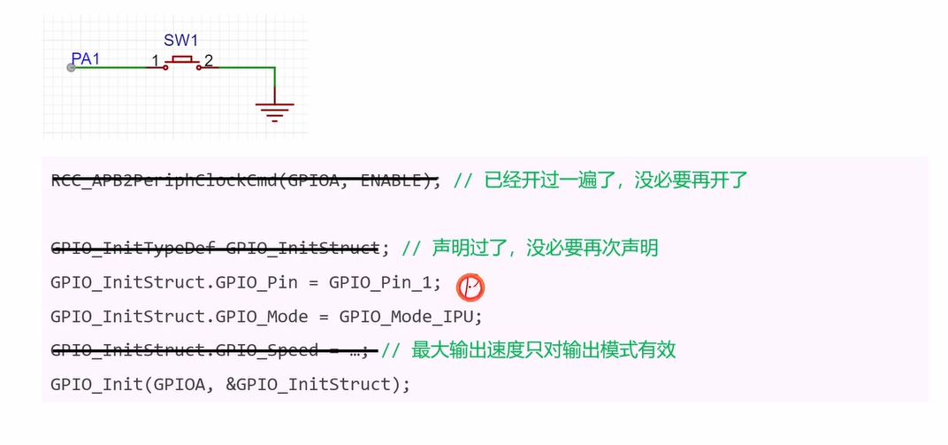
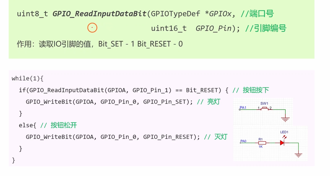
代码
#include "stm32f10x.h"                  // Device header
#include "Delay.h"
int main(void)
{//开启时钟RCC_APB2PeriphClockCmd(RCC_APB2Periph_GPIOA,ENABLE);//定义结构体GPIO_InitTypeDef GPIO_InitStruct;GPIO_InitStruct.GPIO_Pin=GPIO_Pin_0;//推挽输出GPIO_InitStruct.GPIO_Mode=GPIO_Mode_Out_PP;GPIO_InitStruct.GPIO_Speed=GPIO_Speed_2MHz;//初始化GPIO_Init(GPIOA,&GPIO_InitStruct);//按钮接的A1GPIO_InitStruct.GPIO_Pin=GPIO_Pin_1;GPIO_InitStruct.GPIO_Mode=GPIO_Mode_IPU;GPIO_Init(GPIOA,&GPIO_InitStruct);while (1){if(GPIO_ReadInputDataBit(GPIOA,GPIO_Pin_1)==Bit_RESET)		GPIO_WriteBit(GPIOA, GPIO_Pin_0, Bit_SET); elseGPIO_WriteBit(GPIOA, GPIO_Pin_0, Bit_RESET); 		}
}