ESP8266(NodeMcu)+GPS模块+TFT屏幕实现GPS码表
前言
去年写过一篇关于使用esp8266(nodemcu)+gps模块+oled屏幕diy的gps定位器的文章.点击回顾 .无奈OLED屏幕太小了,最近刚好有时间又折腾使用TFT屏幕diy了一款gps码表
效果如图

材料准备
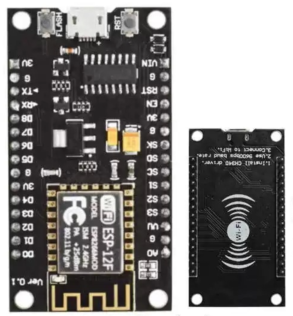
依旧是请出我们的两位老演员
-
nocdmcu一块.
-
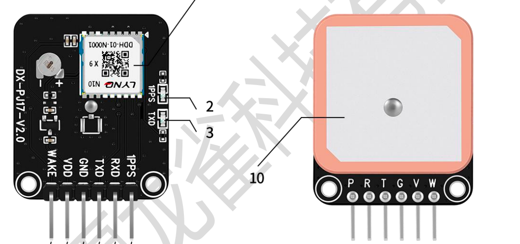
GPS定位模块(我买的大夏龙雀的DX-GP10-GPS模块,某宝有售)
-
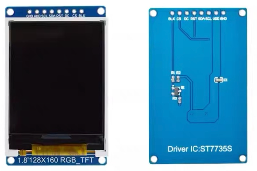
然后是TFT屏幕.尺寸大小为1.8寸.分辨率是128x160.驱动IC为ST7735S
-
杜邦线母对母若干
接线图
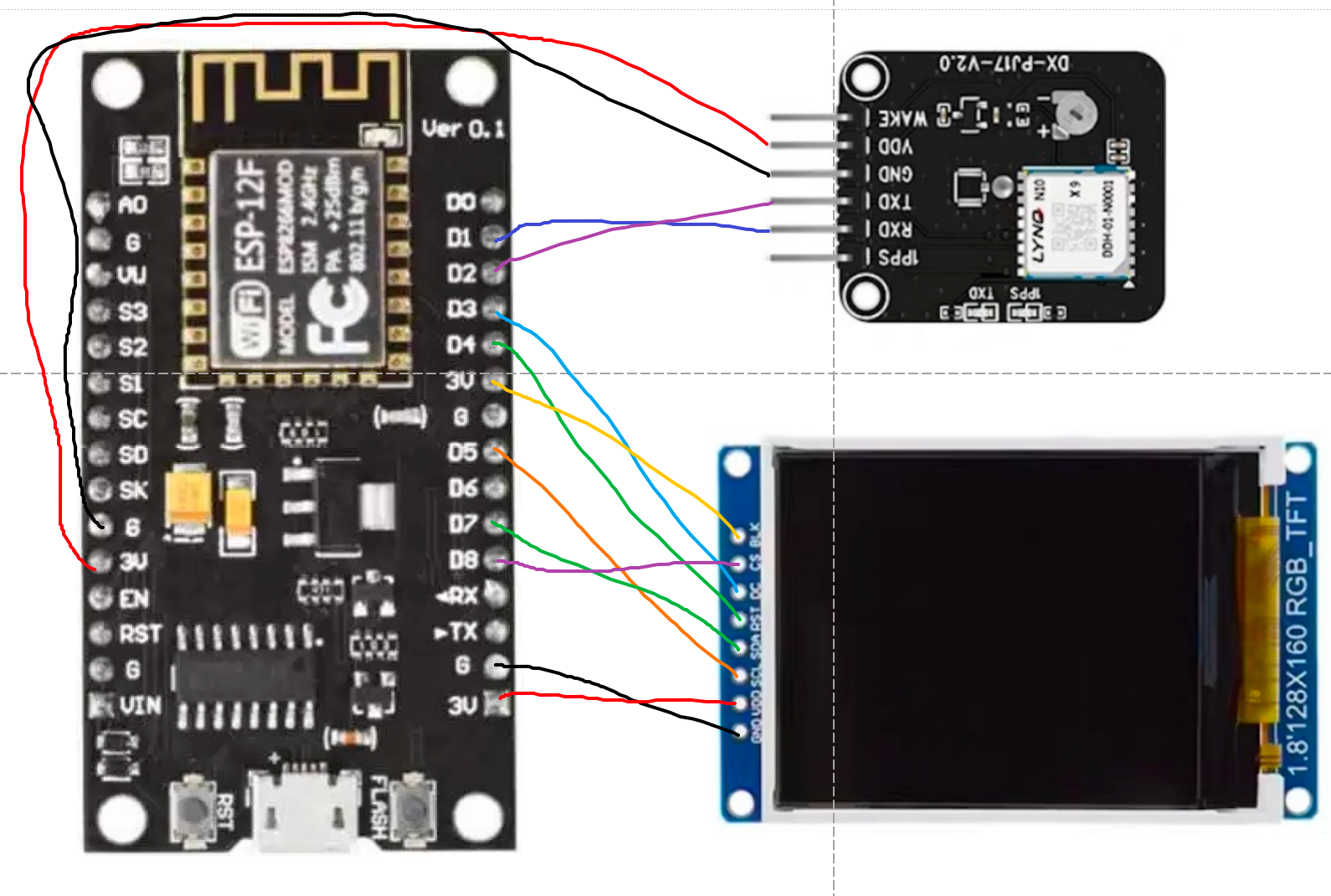
接线说明
| TFT屏幕 | nodemcu |
|---|---|
| GND | GND |
| VCC | 3V3 |
| SCL | D5 |
| SDA | D7 |
| RES | D4 |
| DC | D3 |
| CS | D8 |
| BLK | 3V 可以不接(控制屏幕背光) |
| GPS模块 | nodemcu |
|---|---|
| GND | GND |
| VCC | 3V3 |
| TXD | D2 |
| RXD | D1 |
代码
#include <TFT_eSPI.h>        // TFT库
#include <SoftwareSerial.h>  // 软件串口库
#include <TinyGPS++.h>       // GPS解析库
#include "ESP8266WiFi.h"     // WIFI库// 创建TFT对象
TFT_eSPI tft = TFT_eSPI();// gps模块引脚定义
#define RXPin 4  // GPIO 4 对应nodemcu D2
#define TXPin 5  // GPIO 5 对应nodemcu D1
// 创建软件串口对象用于GPS
SoftwareSerial gpsSerial(RXPin, TXPin);  // RX, TX (根据实际接线调整)// 创建GPS对象
TinyGPSPlus gps;// 卫星信息变量
int usedSatellites = 0;  // 实际用于定位的卫星数量
uint32_t lastSatelliteUpdate = 0;// 变量定义
float currentSpeed = 0.0;       // 当前速度(km/h)
float longitude = 0.0;          // 经度
float latitude = 0.0;           // 纬度
String dateStr = "----/--/--";  // 日期字符串
String timeStr = "--:--:--";    // 时间字符串void setup() {// 初始化串口Serial.begin(115200);//关闭WIFI模块省电WiFi.mode(WIFI_OFF);WiFi.forceSleepBegin();gpsSerial.begin(9600);// 初始化TFT屏幕tft.init();tft.setRotation(1);         // 根据屏幕方向调整tft.fillScreen(TFT_BLACK);  //填充色Serial.println("GPS Speedometer Initialized");
}void loop() {// 读取GPS数据while (gpsSerial.available() > 0) {if (gps.encode(gpsSerial.read())) {updateGPSData();}}// 每500ms刷新一次显示static uint32_t lastUpdate = 0;if (millis() - lastUpdate >= 500) {lastUpdate = millis();updateDisplay();}// 每2秒更新一次卫星信息(不需要太频繁)if (millis() - lastSatelliteUpdate >= 2000) {lastSatelliteUpdate = millis();updateSatelliteInfo();updateSatelliteDisplay();}// 如果长时间没有GPS数据,重置GPS对象if (millis() > 5000 && gps.charsProcessed() < 10) {Serial.println("No GPS data received: check wiring");while (true);}
}// 更新GPS数据
void updateGPSData() {// 经纬度if (gps.location.isValid()) {longitude = gps.location.lng();latitude = gps.location.lat();}// 时速if (gps.speed.isValid()) {currentSpeed = gps.speed.kmph();}if (gps.time.isValid() && gps.date.isValid()) {// UTC时间转换为北京时间// 首先将时间增加8小时byte hour = gps.time.hour() + 8;byte minute = gps.time.minute();byte second = gps.time.second();byte day = gps.date.day();byte month = gps.date.month();int year = gps.date.year();// 处理小时超过24的情况if (hour >= 24) {hour -= 24;day++;// 检查是否需要增加月份if (day > daysInMonth(year, month)) {day = 1;month++;// 检查是否需要增加年份if (month > 12) {month = 1;year++;}}}// 格式化时间字符串char timeBuffer[12];sprintf(timeBuffer, "%02d:%02d:%02d",hour,minute,second);timeStr = String(timeBuffer);// 格式化日期字符串char dateBuffer[12];sprintf(dateBuffer, "%02d/%02d/%02d",year,month,day);dateStr = String(dateBuffer);}
}// 判断是否为闰年
bool isLeapYear(int year) {if (year % 4 != 0) return false;if (year % 100 != 0) return true;return (year % 400 == 0);
}// 获取月份的天数(考虑闰年)
byte daysInMonth(int year, byte month) {const byte monthDays[] = { 31, 28, 31, 30, 31, 30, 31, 31, 30, 31, 30, 31 };if (month == 2 && isLeapYear(year)) {return 29;}return monthDays[month - 1];
}// 更新显示
void updateDisplay() {// 显示日期和时间tft.setTextColor(TFT_CYAN, TFT_BLACK);tft.setTextSize(2);// 日期tft.setCursor(20, 5);tft.print(dateStr);// 时间tft.setCursor(20, 25);tft.print(timeStr);// 分隔线tft.drawFastHLine(0, 50, tft.width(), TFT_DARKGREY);// 显示速度tft.setTextColor(TFT_GREEN, TFT_BLACK);tft.setTextSize(3);tft.setCursor(5, 55);if (currentSpeed < 100 && currentSpeed >= 10) {tft.print(" ");}if (currentSpeed < 10) {tft.print("  ");}tft.print(currentSpeed, 1);tft.setTextSize(2);tft.print(" km/h");// 分隔线tft.drawFastHLine(0, 85, tft.width(), TFT_DARKGREY);// 显示经纬度tft.setTextColor(TFT_YELLOW, TFT_BLACK);tft.setTextSize(1);tft.setCursor(20, 95);tft.print("Lng:");tft.print(longitude, 6);tft.setCursor(20, 115);tft.print("Lat:");tft.print(latitude, 6);
}void updateSatelliteInfo() {// 获取用于定位的卫星数量if (gps.satellites.isValid()) {usedSatellites = gps.satellites.value();} else {usedSatellites = 0;  // 无有效数据时显示0}
}void updateSatelliteDisplay() {// 清空原有显示区域tft.fillRect(120, 95, tft.width(), 20, TFT_BLACK);// 显示卫星信息tft.setTextColor(TFT_CYAN, TFT_BLACK);tft.setTextSize(1);// 卫星图标tft.drawChar(120, 95, 0x47, TFT_CYAN, TFT_BLACK, 1);  // 卫星符号// 使用卫星数量tft.setCursor(125, 95);tft.print("  ");tft.print(usedSatellites);// 根据卫星数量显示状态tft.setCursor(120, 115);if (usedSatellites == 0) {tft.setTextColor(TFT_RED, TFT_BLACK);tft.print("No Fix");} else if (usedSatellites < 4) {tft.setTextColor(TFT_YELLOW, TFT_BLACK);tft.print("Weak");} else {tft.setTextColor(TFT_GREEN, TFT_BLACK);tft.print("Good");}
}
补充说明
nodemcu驱动tft屏幕引入了’TFT_eSPI’库负责驱动屏幕.其中User_Setup.h文件需要按需修改引脚定义.
我贴一下我这边的配置
//                            USER DEFINED SETTINGS
//   Set driver type, fonts to be loaded, pins used and SPI control method etc.
//
//   See the User_Setup_Select.h file if you wish to be able to define multiple
//   setups and then easily select which setup file is used by the compiler.
//
//   If this file is edited correctly then all the library example sketches should
//   run without the need to make any more changes for a particular hardware setup!
//   Note that some sketches are designed for a particular TFT pixel width/height// User defined information reported by "Read_User_Setup" test & diagnostics example
#define USER_SETUP_INFO "User_Setup"// Define to disable all #warnings in library (can be put in User_Setup_Select.h)
//#define DISABLE_ALL_LIBRARY_WARNINGS// ##################################################################################
//
// Section 1. Call up the right driver file and any options for it
//
// ##################################################################################// Define STM32 to invoke optimised processor support (only for STM32)
//#define STM32// Defining the STM32 board allows the library to optimise the performance
// for UNO compatible "MCUfriend" style shields
//#define NUCLEO_64_TFT
//#define NUCLEO_144_TFT// STM32 8-bit parallel only:
// If STN32 Port A or B pins 0-7 are used for 8-bit parallel data bus bits 0-7
// then this will improve rendering performance by a factor of ~8x
//#define STM_PORTA_DATA_BUS
//#define STM_PORTB_DATA_BUS// Tell the library to use parallel mode (otherwise SPI is assumed)
//#define TFT_PARALLEL_8_BIT
//#defined TFT_PARALLEL_16_BIT // **** 16-bit parallel ONLY for RP2040 processor ****// Display type -  only define if RPi display
//#define RPI_DISPLAY_TYPE // 20MHz maximum SPI// Only define one driver, the other ones must be commented out
// #define ILI9341_DRIVER       // Generic driver for common displays
//#define ILI9341_2_DRIVER     // Alternative ILI9341 driver, see https://github.com/Bodmer/TFT_eSPI/issues/1172
#define ST7735_DRIVER      // Define additional parameters below for this display
//#define ILI9163_DRIVER     // Define additional parameters below for this display
//#define S6D02A1_DRIVER
//#define RPI_ILI9486_DRIVER // 20MHz maximum SPI
//#define HX8357D_DRIVER
//#define ILI9481_DRIVER
//#define ILI9486_DRIVER
//#define ILI9488_DRIVER     // WARNING: Do not connect ILI9488 display SDO to MISO if other devices share the SPI bus (TFT SDO does NOT tristate when CS is high)
//#define ST7789_DRIVER      // Full configuration option, define additional parameters below for this display
//#define ST7789_2_DRIVER    // Minimal configuration option, define additional parameters below for this display
//#define R61581_DRIVER
//#define RM68140_DRIVER
//#define ST7796_DRIVER
//#define SSD1351_DRIVER
//#define SSD1963_480_DRIVER
//#define SSD1963_800_DRIVER
//#define SSD1963_800ALT_DRIVER
//#define ILI9225_DRIVER
//#define GC9A01_DRIVER// Some displays support SPI reads via the MISO pin, other displays have a single
// bi-directional SDA pin and the library will try to read this via the MOSI line.
// To use the SDA line for reading data from the TFT uncomment the following line:// #define TFT_SDA_READ      // This option is for ESP32 ONLY, tested with ST7789 and GC9A01 display only// For ST7735, ST7789 and ILI9341 ONLY, define the colour order IF the blue and red are swapped on your display
// Try ONE option at a time to find the correct colour order for your display#define TFT_RGB_ORDER TFT_RGB  // Colour order Red-Green-Blue
//  #define TFT_RGB_ORDER TFT_BGR  // Colour order Blue-Green-Red// For M5Stack ESP32 module with integrated ILI9341 display ONLY, remove // in line below// #define M5STACK// For ST7789, ST7735, ILI9163 and GC9A01 ONLY, define the pixel width and height in portrait orientation
// #define TFT_WIDTH  80#define TFT_WIDTH  128
// #define TFT_WIDTH  172 // ST7789 172 x 320
// #define TFT_WIDTH  170 // ST7789 170 x 320
// #define TFT_WIDTH  240 // ST7789 240 x 240 and 240 x 320#define TFT_HEIGHT 160
// #define TFT_HEIGHT 128
// #define TFT_HEIGHT 240 // ST7789 240 x 240
// #define TFT_HEIGHT 320 // ST7789 240 x 320
// #define TFT_HEIGHT 240 // GC9A01 240 x 240// For ST7735 ONLY, define the type of display, originally this was based on the
// colour of the tab on the screen protector film but this is not always true, so try
// out the different options below if the screen does not display graphics correctly,
// e.g. colours wrong, mirror images, or stray pixels at the edges.
// Comment out ALL BUT ONE of these options for a ST7735 display driver, save this
// this User_Setup file, then rebuild and upload the sketch to the board again:// #define ST7735_INITB
// #define ST7735_GREENTAB
// #define ST7735_GREENTAB2
// #define ST7735_GREENTAB3
// #define ST7735_GREENTAB128    // For 128 x 128 display
// #define ST7735_GREENTAB160x80 // For 160 x 80 display (BGR, inverted, 26 offset)
// #define ST7735_ROBOTLCD       // For some RobotLCD Arduino shields (128x160, BGR, https://docs.arduino.cc/retired/getting-started-guides/TFT)
// #define ST7735_REDTAB
// #define ST7735_BLACKTAB
// #define ST7735_REDTAB160x80   // For 160 x 80 display with 24 pixel offset// If colours are inverted (white shows as black) then uncomment one of the next
// 2 lines try both options, one of the options should correct the inversion.// #define TFT_INVERSION_ON
// #define TFT_INVERSION_OFF// ##################################################################################
//
// Section 2. Define the pins that are used to interface with the display here
//
// ##################################################################################// If a backlight control signal is available then define the TFT_BL pin in Section 2
// below. The backlight will be turned ON when tft.begin() is called, but the library
// needs to know if the LEDs are ON with the pin HIGH or LOW. If the LEDs are to be
// driven with a PWM signal or turned OFF/ON then this must be handled by the user
// sketch. e.g. with digitalWrite(TFT_BL, LOW);// #define TFT_BL   32            // LED back-light control pin
// #define TFT_BACKLIGHT_ON HIGH  // Level to turn ON back-light (HIGH or LOW)// We must use hardware SPI, a minimum of 3 GPIO pins is needed.
// Typical setup for ESP8266 NodeMCU ESP-12 is :
//
// Display SDO/MISO  to NodeMCU pin D6 (or leave disconnected if not reading TFT)
// Display LED       to NodeMCU pin VIN (or 5V, see below)
// Display SCK       to NodeMCU pin D5
// Display SDI/MOSI  to NodeMCU pin D7
// Display DC (RS/AO)to NodeMCU pin D3
// Display RESET     to NodeMCU pin D4 (or RST, see below)
// Display CS        to NodeMCU pin D8 (or GND, see below)
// Display GND       to NodeMCU pin GND (0V)
// Display VCC       to NodeMCU 5V or 3.3V
//
// The TFT RESET pin can be connected to the NodeMCU RST pin or 3.3V to free up a control pin
//
// The DC (Data Command) pin may be labelled AO or RS (Register Select)
//
// With some displays such as the ILI9341 the TFT CS pin can be connected to GND if no more
// SPI devices (e.g. an SD Card) are connected, in this case comment out the #define TFT_CS
// line below so it is NOT defined. Other displays such at the ST7735 require the TFT CS pin
// to be toggled during setup, so in these cases the TFT_CS line must be defined and connected.
//
// The NodeMCU D0 pin can be used for RST
//
//
// Note: only some versions of the NodeMCU provide the USB 5V on the VIN pin
// If 5V is not available at a pin you can use 3.3V but backlight brightness
// will be lower.// ###### EDIT THE PIN NUMBERS IN THE LINES FOLLOWING TO SUIT YOUR ESP8266 SETUP ######// For NodeMCU - use pin numbers in the form PIN_Dx where Dx is the NodeMCU pin designation
#define TFT_MISO  PIN_D6  // Automatically assigned with ESP8266 if not defined
#define TFT_MOSI  PIN_D7  // Automatically assigned with ESP8266 if not defined
#define TFT_SCLK  PIN_D5  // Automatically assigned with ESP8266 if not defined#define TFT_CS    PIN_D8  // Chip select control pin D8
#define TFT_DC    PIN_D3  // Data Command control pin
#define TFT_RST   PIN_D4  // Reset pin (could connect to NodeMCU RST, see next line)
//#define TFT_RST  -1     // Set TFT_RST to -1 if the display RESET is connected to NodeMCU RST or 3.3V//#define TFT_BL PIN_D1  // LED back-light (only for ST7789 with backlight control pin)//#define TOUCH_CS PIN_D2     // Chip select pin (T_CS) of touch screen//#define TFT_WR PIN_D2       // Write strobe for modified Raspberry Pi TFT only// ######  FOR ESP8266 OVERLAP MODE EDIT THE PIN NUMBERS IN THE FOLLOWING LINES  ######// Overlap mode shares the ESP8266 FLASH SPI bus with the TFT so has a performance impact
// but saves pins for other functions. It is best not to connect MISO as some displays
// do not tristate that line when chip select is high!
// Note: Only one SPI device can share the FLASH SPI lines, so a SPI touch controller
// cannot be connected as well to the same SPI signals.
// On NodeMCU 1.0 SD0=MISO, SD1=MOSI, CLK=SCLK to connect to TFT in overlap mode
// On NodeMCU V3  S0 =MISO, S1 =MOSI, S2 =SCLK
// In ESP8266 overlap mode the following must be defined//#define TFT_SPI_OVERLAP// In ESP8266 overlap mode the TFT chip select MUST connect to pin D3
//#define TFT_CS   PIN_D3
//#define TFT_DC   PIN_D5  // Data Command control pin
//#define TFT_RST  PIN_D4  // Reset pin (could connect to NodeMCU RST, see next line)
//#define TFT_RST  -1  // Set TFT_RST to -1 if the display RESET is connected to NodeMCU RST or 3.3V// ###### EDIT THE PIN NUMBERS IN THE LINES FOLLOWING TO SUIT YOUR ESP32 SETUP   ######// For ESP32 Dev board (only tested with ILI9341 display)
// The hardware SPI can be mapped to any pins//#define TFT_MISO 19
//#define TFT_MOSI 23
//#define TFT_SCLK 18
//#define TFT_CS   15  // Chip select control pin
//#define TFT_DC    2  // Data Command control pin
//#define TFT_RST   4  // Reset pin (could connect to RST pin)
//#define TFT_RST  -1  // Set TFT_RST to -1 if display RESET is connected to ESP32 board RST// For ESP32 Dev board (only tested with GC9A01 display)
// The hardware SPI can be mapped to any pins//#define TFT_MOSI 15 // In some display driver board, it might be written as "SDA" and so on.
//#define TFT_SCLK 14
//#define TFT_CS   5  // Chip select control pin
//#define TFT_DC   27  // Data Command control pin
//#define TFT_RST  33  // Reset pin (could connect to Arduino RESET pin)
//#define TFT_BL   22  // LED back-light//#define TOUCH_CS 21     // Chip select pin (T_CS) of touch screen//#define TFT_WR 22    // Write strobe for modified Raspberry Pi TFT only// For the M5Stack module use these #define lines
//#define TFT_MISO 19
//#define TFT_MOSI 23
//#define TFT_SCLK 18
//#define TFT_CS   14  // Chip select control pin
//#define TFT_DC   27  // Data Command control pin
//#define TFT_RST  33  // Reset pin (could connect to Arduino RESET pin)
//#define TFT_BL   32  // LED back-light (required for M5Stack)// ######       EDIT THE PINs BELOW TO SUIT YOUR ESP32 PARALLEL TFT SETUP        ######// The library supports 8-bit parallel TFTs with the ESP32, the pin
// selection below is compatible with ESP32 boards in UNO format.
// Wemos D32 boards need to be modified, see diagram in Tools folder.
// Only ILI9481 and ILI9341 based displays have been tested!// Parallel bus is only supported for the STM32 and ESP32
// Example below is for ESP32 Parallel interface with UNO displays// Tell the library to use 8-bit parallel mode (otherwise SPI is assumed)
//#define TFT_PARALLEL_8_BIT// The ESP32 and TFT the pins used for testing are:
//#define TFT_CS   33  // Chip select control pin (library pulls permanently low
//#define TFT_DC   15  // Data Command control pin - must use a pin in the range 0-31
//#define TFT_RST  32  // Reset pin, toggles on startup//#define TFT_WR    4  // Write strobe control pin - must use a pin in the range 0-31
//#define TFT_RD    2  // Read strobe control pin//#define TFT_D0   12  // Must use pins in the range 0-31 for the data bus
//#define TFT_D1   13  // so a single register write sets/clears all bits.
//#define TFT_D2   26  // Pins can be randomly assigned, this does not affect
//#define TFT_D3   25  // TFT screen update performance.
//#define TFT_D4   17
//#define TFT_D5   16
//#define TFT_D6   27
//#define TFT_D7   14// ######       EDIT THE PINs BELOW TO SUIT YOUR STM32 SPI TFT SETUP        ######// The TFT can be connected to SPI port 1 or 2
//#define TFT_SPI_PORT 1 // SPI port 1 maximum clock rate is 55MHz
//#define TFT_MOSI PA7
//#define TFT_MISO PA6
//#define TFT_SCLK PA5//#define TFT_SPI_PORT 2 // SPI port 2 maximum clock rate is 27MHz
//#define TFT_MOSI PB15
//#define TFT_MISO PB14
//#define TFT_SCLK PB13// Can use Ardiuno pin references, arbitrary allocation, TFT_eSPI controls chip select
//#define TFT_CS   D5 // Chip select control pin to TFT CS
//#define TFT_DC   D6 // Data Command control pin to TFT DC (may be labelled RS = Register Select)
//#define TFT_RST  D7 // Reset pin to TFT RST (or RESET)
// OR alternatively, we can use STM32 port reference names PXnn
//#define TFT_CS   PE11 // Nucleo-F767ZI equivalent of D5
//#define TFT_DC   PE9  // Nucleo-F767ZI equivalent of D6
//#define TFT_RST  PF13 // Nucleo-F767ZI equivalent of D7//#define TFT_RST  -1   // Set TFT_RST to -1 if the display RESET is connected to processor reset// Use an Arduino pin for initial testing as connecting to processor reset// may not work (pulse too short at power up?)// ##################################################################################
//
// Section 3. Define the fonts that are to be used here
//
// ##################################################################################// Comment out the #defines below with // to stop that font being loaded
// The ESP8366 and ESP32 have plenty of memory so commenting out fonts is not
// normally necessary. If all fonts are loaded the extra FLASH space required is
// about 17Kbytes. To save FLASH space only enable the fonts you need!#define LOAD_GLCD   // Font 1. Original Adafruit 8 pixel font needs ~1820 bytes in FLASH
#define LOAD_FONT2  // Font 2. Small 16 pixel high font, needs ~3534 bytes in FLASH, 96 characters
#define LOAD_FONT4  // Font 4. Medium 26 pixel high font, needs ~5848 bytes in FLASH, 96 characters
#define LOAD_FONT6  // Font 6. Large 48 pixel font, needs ~2666 bytes in FLASH, only characters 1234567890:-.apm
#define LOAD_FONT7  // Font 7. 7 segment 48 pixel font, needs ~2438 bytes in FLASH, only characters 1234567890:-.
#define LOAD_FONT8  // Font 8. Large 75 pixel font needs ~3256 bytes in FLASH, only characters 1234567890:-.
//#define LOAD_FONT8N // Font 8. Alternative to Font 8 above, slightly narrower, so 3 digits fit a 160 pixel TFT
#define LOAD_GFXFF  // FreeFonts. Include access to the 48 Adafruit_GFX free fonts FF1 to FF48 and custom fonts// Comment out the #define below to stop the SPIFFS filing system and smooth font code being loaded
// this will save ~20kbytes of FLASH
#define SMOOTH_FONT// ##################################################################################
//
// Section 4. Other options
//
// ##################################################################################// For RP2040 processor and SPI displays, uncomment the following line to use the PIO interface.
//#define RP2040_PIO_SPI // Leave commented out to use standard RP2040 SPI port interface// For RP2040 processor and 8 or 16-bit parallel displays:
// The parallel interface write cycle period is derived from a division of the CPU clock
// speed so scales with the processor clock. This means that the divider ratio may need
// to be increased when overclocking. It may also need to be adjusted dependant on the
// display controller type (ILI94341, HX8357C etc.). If RP2040_PIO_CLK_DIV is not defined
// the library will set default values which may not suit your display.
// The display controller data sheet will specify the minimum write cycle period. The
// controllers often work reliably for shorter periods, however if the period is too short
// the display may not initialise or graphics will become corrupted.
// PIO write cycle frequency = (CPU clock/(4 * RP2040_PIO_CLK_DIV))
//#define RP2040_PIO_CLK_DIV 1 // 32ns write cycle at 125MHz CPU clock
//#define RP2040_PIO_CLK_DIV 2 // 64ns write cycle at 125MHz CPU clock
//#define RP2040_PIO_CLK_DIV 3 // 96ns write cycle at 125MHz CPU clock// For the RP2040 processor define the SPI port channel used (default 0 if undefined)
//#define TFT_SPI_PORT 1 // Set to 0 if SPI0 pins are used, or 1 if spi1 pins used// For the STM32 processor define the SPI port channel used (default 1 if undefined)
//#define TFT_SPI_PORT 2 // Set to 1 for SPI port 1, or 2 for SPI port 2// Define the SPI clock frequency, this affects the graphics rendering speed. Too
// fast and the TFT driver will not keep up and display corruption appears.
// With an ILI9341 display 40MHz works OK, 80MHz sometimes fails
// With a ST7735 display more than 27MHz may not work (spurious pixels and lines)
// With an ILI9163 display 27 MHz works OK.// #define SPI_FREQUENCY   1000000
// #define SPI_FREQUENCY   5000000
// #define SPI_FREQUENCY  10000000
// #define SPI_FREQUENCY  20000000
#define SPI_FREQUENCY  27000000
// #define SPI_FREQUENCY  40000000
// #define SPI_FREQUENCY  55000000 // STM32 SPI1 only (SPI2 maximum is 27MHz)
// #define SPI_FREQUENCY  80000000// Optional reduced SPI frequency for reading TFT
#define SPI_READ_FREQUENCY  20000000// The XPT2046 requires a lower SPI clock rate of 2.5MHz so we define that here:
#define SPI_TOUCH_FREQUENCY  2500000// The ESP32 has 2 free SPI ports i.e. VSPI and HSPI, the VSPI is the default.
// If the VSPI port is in use and pins are not accessible (e.g. TTGO T-Beam)
// then uncomment the following line:
//#define USE_HSPI_PORT// Comment out the following #define if "SPI Transactions" do not need to be
// supported. When commented out the code size will be smaller and sketches will
// run slightly faster, so leave it commented out unless you need it!// Transaction support is needed to work with SD library but not needed with TFT_SdFat
// Transaction support is required if other SPI devices are connected.// Transactions are automatically enabled by the library for an ESP32 (to use HAL mutex)
// so changing it here has no effect// #define SUPPORT_TRANSACTIONS
完整代码可以看我的码云地址:https://gitee.com/hailongg/esp8266-demo