Apollo平台下相机和激光雷达手眼联合标定
Apollo平台下相机和激光雷达手眼联合标定:原理与实战指南
- 一、为什么要进行相机-激光雷达联合标定?
- 二、标定原理概述
- 1. 坐标系定义
- 2. 核心数学模型
- 2.1 相机投影方程(3D→2D)
- 2.2 刚体变换方程(激光雷达→相机)
- 3. 标定原理实现路径
- 3.1 建立共同参考系(标定板)
- 3.2 求解相机→标定板变换(T_{c←w})
- 3.3 求解激光雷达→标定板变换(T_{l←w})
- 3.4 求解最终变换(T_{c←l})
- 三、完整标定流程
- 步骤1:数据采集 - 录制传感器数据
- 步骤2:数据预处理 - 提取图像与点云
- 步骤3:相机内参标定
- 步骤4:选取3D-2D对应点
- 4.1 在点云中选取3D点
- 4.2 在图像中选取对应2D点
- 步骤5:计算相机到激光雷达的变换矩阵
- 四、标定结果验证
- 五、进阶技巧
- 六、结语
本文详细介绍了在Apollo自动驾驶平台上进行相机与激光雷达联合标定的完整流程,从基础原理到实际操作步骤,帮助读者理解并掌握多传感器融合的关键技术。
一、为什么要进行相机-激光雷达联合标定?
在自动驾驶系统中,相机提供丰富的纹理和颜色信息,而激光雷达提供精确的三维空间信息。两者协同工作能实现更强大的环境感知能力。但要使它们的感知结果准确对齐,必须解决一个核心问题:
如何确定相机和激光雷达之间的空间关系?
这就是手眼标定的核心目标 - 找到相机坐标系与激光雷达坐标系之间的精确变换关系(旋转矩阵和平移向量)。没有这个变换关系,系统就无法正确地将激光雷达点云投影到图像上(反之亦然),导致感知结果错位。
二、标定原理概述
1. 坐标系定义
在标定系统中,我们定义三个关键坐标系:
- 相机坐标系 ©:原点在相机光心,Z轴沿光轴方向
- 激光雷达坐标系 (L):原点在激光雷达中心
- 世界坐标系 (W):通常以标定板为参考
2. 核心数学模型
联合标定的数学模型包含两个关键方程:
2.1 相机投影方程(3D→2D)
相机将3D世界点投影到2D图像平面:
⎡ u ⎤   ⎡ f_x  0   c_x ⎤ ⎡ r11  r12  r13  t_x ⎤ ⎡ X_w ⎤
⎢ v ⎥ = ⎢ 0   f_y c_y  ⎥ ⎢ r21  r22  r23  t_y ⎥ ⎢ Y_w ⎥
⎣ 1 ⎦   ⎣ 0    0    1  ⎦ ⎣ r31  r32  r33  t_z ⎦ ⎢ Z_w ⎥⎣  1  ⎦
其中:
(u, v):图像像素坐标(X_w, Y_w, Z_w):世界坐标系中的3D点坐标f_x, f_y:焦距(像素单位)c_x, c_y:主点坐标(图像中心)r_ij:旋转矩阵元素(世界坐标系到相机坐标系的旋转)t_x, t_y, t_z:平移向量元素(世界坐标系到相机坐标系的平移)
参数矩阵分解:
- 内参矩阵 K:
K = ⎡ f_x 0 c_x ⎤⎢ 0 f_y c_y ⎥⎣ 0 0 1 ⎦ - 外参矩阵 [R|t]:
[R|t] = ⎡ r11 r12 r13 t_x ⎤⎢ r21 r22 r23 t_y ⎥⎣ r31 r32 r33 t_z ⎦
2.2 刚体变换方程(激光雷达→相机)
标定的核心目标是求解激光雷达到相机的变换矩阵:
P_c = T_{c←l} * P_l
其中:
P_c:点在相机坐标系的坐标P_l:点在激光雷达坐标系的坐标T_{c←l}:激光雷达到相机的4×4齐次变换矩阵
变换矩阵的具体形式:
T_{c←l} = ⎡ R_{c←l} t_{c←l} ⎤⎣ 0 1 ⎦
R_{c←l}:3×3旋转矩阵(激光雷达到相机)t_{c←l}:3×1平移向量(激光雷达到相机)
3. 标定原理实现路径
3.1 建立共同参考系(标定板)
我们使用标定板作为中介,建立两个传感器之间的关联:
相机 ← 标定板 → 激光雷达
数学表达:
P_c = T_{c←w} * P_w
P_l = T_{l←w} * P_w
3.2 求解相机→标定板变换(T_{c←w})
通过相机标定求解:
# 使用棋盘格角点求解
ret, rvec, tvec = cv2.solvePnP(object_points,    # 世界坐标系中的3D点image_points,     # 图像中的2D点camera_matrix,    # 相机内参Kdist_coeffs       # 畸变系数
)# 将旋转向量转换为矩阵
R_cw, _ = cv2.Rodrigues(rvec)
T_cw = np.eye(4)
T_cw[:3, :3] = R_cw
T_cw[:3, 3] = tvec.flatten()
3.3 求解激光雷达→标定板变换(T_{l←w})
通过点云选取标定板角点:
在激光雷达坐标系中直接测量标定板角点的3D坐标
3.4 求解最终变换(T_{c←l})
通过变换链求解:
T_{c←l} = T_{c←w} * T_{w←l} = T_{c←w} * inv(T_{l←w})
数学推导:
P_c = T_{c←w} * P_w
P_l = T_{l←w} * P_w  =>  P_w = T_{w←l} * P_l = inv(T_{l←w}) * P_l代入得:
P_c = T_{c←w} * inv(T_{l←w}) * P_l
∴ T_{c←l} = T_{c←w} * inv(T_{l←w})
三、完整标定流程
步骤1:数据采集 - 录制传感器数据
# 查看记录文件信息(确认包含所需传感器数据)cyber_recorder info ~/.apollo/resources/records/bev_test.record -l# 回放数据(测试数据可用性)
cyber_recorder  play -f ~/.apollo/resources/records/bev_test.record -l# 录制所需传感器数据(相机图像+激光雷达点云)
cyber_recorder record -c /apollo/sensor/camera/CAM_FRONT/image \/apollo/sensor/LIDAR_TOP/compensator/PointCloud2 \-o front.record
关键参数说明:
-c:指定要录制的数据通道-o:输出记录文件名- 最佳实践:录制时使用棋盘格标定板,确保同时出现在相机和激光雷达视野中
步骤2:数据预处理 - 提取图像与点云
import sys
import os
sys.path.append("/opt/apollo/neo/python/cyber/python")
sys.path.append("/opt/apollo/neo/python")
from cyber_py3 import cyber
from modules.common_msgs.sensor_msgs import pointcloud_pb2
from modules.common_msgs.transform_msgs import transform_pb2
from modules.common_msgs.localization_msgs import localization_pb2
from modules.common_msgs.sensor_msgs import sensor_image_pb2
from google.protobuf import descriptor as _descriptor
from google.protobuf import message as _message
import cv2
import numpy as np
from cyber.python.cyber_py3 import record
import time
import cv2
import numpy as np
import open3d as o3d# 彩虹色映射示例
def intensity_to_rainbow(intensity, min_val, max_val):ratio = (intensity - min_val) / (max_val - min_val)r = np.clip(1.5 - np.abs(2 * ratio - 1), 0, 1)g = np.clip(1.5 - np.abs(2 * ratio - 0.5), 0, 1)b = np.clip(1.5 - np.abs(2 * ratio - 1.5), 0, 1)return [r, g, b]def extract_image(record_path, output_dir="./"):    cam_cache={}# 创建record读取器reader = record.RecordReader(record_path)for msg in reader.read_messages():if msg.topic=="/apollo/sensor/camera/CAM_FRONT/image":image_msg = sensor_image_pb2.Image()image_msg.ParseFromString(msg.message)print("image_msg.header.timestamp_sec=",image_msg.header.timestamp_sec)print("image_msg.header.module_name=",image_msg.header.module_name)print("image_msg.header.sequence_num=",image_msg.header.sequence_num)print("image_msg.header.lidar_timestamp=",image_msg.header.lidar_timestamp)print("image_msg.header.camera_timestamp=",image_msg.header.camera_timestamp)print("image_msg.header.radar_timestamp=",image_msg.header.radar_timestamp)print("image_msg.header.version=",image_msg.header.version)print("image_msg.header.status=",image_msg.header.status)print("image_msg.header.frame_id=",image_msg.header.frame_id)img_data = np.frombuffer(image_msg.data,\dtype=np.uint8).reshape((image_msg.height,image_msg.width,-1))# 保存图像(使用时间戳命名确保同步)cv2.imwrite(f"{image_msg.measurement_time}.cam.jpg",img_data[:,:,::-1])   if msg.topic=="/apollo/sensor/LIDAR_TOP/compensator/PointCloud2":pc = pointcloud_pb2.PointCloud()pc.ParseFromString(msg.message)print("pc.header.timestamp_sec=",pc.header.timestamp_sec)print("pc.header.module_name=",pc.header.module_name)print("pc.header.sequence_num=",pc.header.sequence_num)print("pc.header.lidar_timestamp=",pc.header.lidar_timestamp)print("pc.header.camera_timestamp=",pc.header.camera_timestamp)print("pc.header.version=",pc.header.version)print("pc.header.status=",pc.header.status)print("pc.header.frame_id=",pc.header.frame_id)# 提取点云数据points = []intensities = []timestamps = []for pt in pc.point:# 处理 NaN 值 (转换为 0)x = pt.x if not np.isnan(pt.x) else 0.0y = pt.y if not np.isnan(pt.y) else 0.0z = pt.z if not np.isnan(pt.z) else 0.0        points.append([x, y, z])intensities.append(pt.intensity)timestamps.append(pt.timestamp)# 转换为 numpy 数组points = np.array(points, dtype=np.float32)intensities = np.array(intensities, dtype=np.float32)# 创建 Open3D 点云对象pcd = o3d.geometry.PointCloud()pcd.points = o3d.utility.Vector3dVector(points)# 基于强度值生成颜色 (灰度映射)if len(intensities) > 0:# 归一化强度值到 0-1 范围min_intensity = np.min(intensities)max_intensity = np.max(intensities)if max_intensity - min_intensity > 1e-6:normalized_intensity = (intensities - min_intensity) / (max_intensity - min_intensity)else:normalized_intensity = np.zeros_like(intensities)# 创建灰度颜色 (R=G=B)colors = np.zeros((len(points), 3))colors[:, 0] = normalized_intensity  # Rcolors[:, 1] = normalized_intensity  # Gcolors[:, 2] = normalized_intensity  # B# 彩虹色映射colors = np.array([intensity_to_rainbow(i, min_intensity, max_intensity) for i in intensities])                pcd.colors = o3d.utility.Vector3dVector(colors)# 保存为 PLY 格式 (支持颜色)# 保存点云(使用时间戳命名)o3d.io.write_point_cloud(f"{pc.measurement_time}.pc.pcd", pcd,write_ascii=True)if __name__ == "__main__":if len(sys.argv)!=2:print(f"Usage:{sys.argv[0]} record_path")else:extract_image(record_path=sys.argv[1])
处理说明:
- 使用时间戳命名确保图像和点云的时间对齐
- 点云强度值映射为彩虹色,便于人工检查点云质量
- 处理NaN值避免后续计算错误
步骤3:相机内参标定
import numpy as np
import cv2
import glob# 设置棋盘格参数
chessboard_size = (8, 6)  # 内部角点数量 (列, 行)
square_size = 0.02        # 每个方格的实际大小(米)# 准备世界坐标系中的点 (0,0,0), (0.02,0,0), (0.04,0,0), ..., (0.14,0.10,0)
objp = np.zeros((chessboard_size[0] * chessboard_size[1], 3), np.float32)
objp[:, :2] = np.mgrid[0:chessboard_size[0], 0:chessboard_size[1]].T.reshape(-1, 2) * square_size# 存储所有图像的对象点和图像点
objpoints = []  # 真实世界中的3D点
imgpoints = []  # 图像中的2D点# 读取所有标定图片
images = glob.glob('images/*.png')  # 修改为你的图片路径for fname in images:img = cv2.imread(fname)gray = cv2.cvtColor(img, cv2.COLOR_BGR2GRAY)# 查找棋盘格角点ret, corners = cv2.findChessboardCorners(gray, chessboard_size, None)# 如果找到,添加对象点和图像点if ret:objpoints.append(objp)# 提高角点检测精度criteria = (cv2.TERM_CRITERIA_EPS + cv2.TERM_CRITERIA_MAX_ITER, 30, 0.001)corners2 = cv2.cornerSubPix(gray, corners, (11,11), (-1,-1), criteria)imgpoints.append(corners2)# 可视化角点(可选)cv2.drawChessboardCorners(img, chessboard_size, corners2, ret)cv2.imshow('Corners', img)cv2.waitKey(-1)  # 显示0.5秒cv2.destroyAllWindows()# 进行相机标定
ret, mtx, dist, rvecs, tvecs = cv2.calibrateCamera(objpoints, imgpoints, gray.shape[::-1], None, None
)# 打印内参矩阵
print("相机内参矩阵 (K):")
print(mtx)# 打印畸变系数
print("\n畸变系数:")
print(dist)# 计算重投影误差
mean_error = 0
for i in range(len(objpoints)):imgpoints2, _ = cv2.projectPoints(objpoints[i], rvecs[i], tvecs[i], mtx, dist)error = cv2.norm(imgpoints[i], imgpoints2, cv2.NORM_L2) / len(imgpoints2)mean_error += errorprint("\n平均重投影误差: {:.5f} 像素".format(mean_error / len(objpoints)))# 保存结果
np.savez('camera_params.npz', mtx=mtx, dist=dist)
关键点说明:
- 棋盘格选择:内部角点数量应足够多(推荐8×6以上)
- 亚像素优化:提高角点检测精度
- 重投影误差:评估标定质量,小于0.5像素为优秀
- 畸变系数:补偿镜头畸变,提升图像精度
步骤4:选取3D-2D对应点
4.1 在点云中选取3D点
- 使用CloudCompare打开点云文件
- 找到标定板角点或其他明显特征点
- 使用"Point List Picking"工具记录坐标
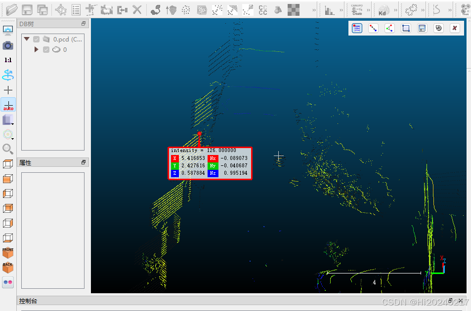
注意事项:
- 至少选择4个非共面点(推荐9-12个点)
- 选择高反射率、位置明确的点
- 保存点坐标为N×3矩阵格式
4.2 在图像中选取对应2D点
- 打开对应时间戳的图像文件
- 使用图像标注工具标注与3D点对应的像素位置
- 记录像素坐标(u, v)
# 示例对应点数据结构
object_points = np.array([  # 3D点 (x, y, z)[1.235, 0.456, 0.789],[1.210, 0.432, 0.801],[1.198, 0.421, 0.795],[1.225, 0.443, 0.782]
], dtype=np.float32)image_points = np.array([  # 2D点 (u, v)[345.6, 210.3],[360.2, 205.7],[372.8, 208.1],[350.1, 215.9]
], dtype=np.float32)
步骤5:计算相机到激光雷达的变换矩阵
# 从相机标定获取的参数
camera_matrix = np.array([[1368.69, 0, 975.43],[0, 1375.52, 423.65],[0, 0, 1]
])dist_coeffs = np.array([0.005, -0.084, -0.015, 0.001, 0.000])# 使用PnP算法求解外参
success, rotation_vec, translation_vec = cv2.solvePnP(object_points, image_points,camera_matrix,dist_coeffs
)if not success:raise RuntimeError("PnP算法求解失败!请检查输入点")# 将旋转向量转换为旋转矩阵
rotation_mat, _ = cv2.Rodrigues(rotation_vec)print("旋转矩阵 (R):")
print(rotation_mat)print("\n平移向量 (t):")
print(translation_vec)# 构建完整的4×4变换矩阵
transform_matrix = np.eye(4)
transform_matrix[:3, :3] = rotation_mat
transform_matrix[:3, 3] = translation_vec.flatten()print("\n相机到激光雷达的变换矩阵:")
print(transform_matrix)
算法原理说明:
PnP(Perspective-n-Point)算法通过最小化重投影误差求解相机位姿:
min Σ ||proj(X_i) - x_i||²
其中:
proj():相机投影函数X_i:3D点坐标x_i:对应2D点坐标
四、标定结果验证
-
点云投影验证:
# 将点云投影到图像 projected_points, _ = cv2.projectPoints(object_points,rotation_vec,translation_vec,camera_matrix,dist_coeffs )# 在图像上绘制投影点 for pt in projected_points.squeeze():cv2.circle(img, tuple(pt.astype(int)), 5, (0, 255, 0), -1)cv2.imshow('Projection Check', img) cv2.waitKey(0) -
误差评估指标:
- 平均投影误差:应 < 2像素
- 角点对齐度:目视检查点云角点与图像角点对齐程度
五、进阶技巧
-
自动特征检测:
- 使用OpenCV的aruco模块替代棋盘格
- 实现角点自动检测算法
-
多位置联合优化:
# 使用多组数据优化外参 retval, rotation_vec, translation_vec = cv2.solvePnPGeneric(object_points, image_points,camera_matrix,dist_coeffs,flags=cv2.SOLVEPNP_ITERATIVE,useExtrinsicGuess=False ) -
时间同步优化:
- 使用PTP协议实现硬件级时间同步
- 在数据采集时添加硬件触发信号
六、结语
相机与激光雷达的精确标定是实现多传感器融合的基础。通过本文介绍的完整流程:
- 理解了手眼标定的基本原理
- 掌握了Apollo平台下的数据采集方法
- 实践了从数据预处理到参数计算的全过程
- 学会了标定结果验证与优化技巧
精确的标定不仅能提升感知系统性能,还能为后续的SLAM、目标检测等模块奠定坚实基础。建议每隔3-6个月或在传感器位置调整后重新标定,以保持系统最佳性能。