rt-thread 5.2.1 基于at-start-f437开发过程记录
基于rt-thread 5.2.1 bsp/at/at32f437-start进行开发,记录详细过程,包括中间遇到的各种坑。
at32f437-start原理图
自己设计的电路板主要换了一块小封装的同系列芯片, 目标是移植opENer。
1. 开发环境
env长时间不用,有点忘了。这次新下载了个2.0新版本。
软件包列表更新,现在新加入的包很多,会出现和服务器不同步的情况。本次开发想用的opENer在iot里找不到,就需要更新。
软件包更新和下载
pkgs --upgrade 命令更新软件包列表
项目menuconfig选中相应的包后,需要下载。
pkgs --update 命令会自动更新/下载/删除相关软件包
2.项目配置
启动ENV,进入bsp目录,这儿选择/bsp/at32/at32f437-start。menuconfig配置,项目硬件有uart,emac,pin,内部falsh,软件包选了opENer。
从rt-thread 5.2.0起,硬件sdk包和以前版本稍有不同,需要通过on packages/peripheral libraries and drivers/HAL & SDK Drivers/AT32HAL & SDK Drivers中选择对应的单片机型号。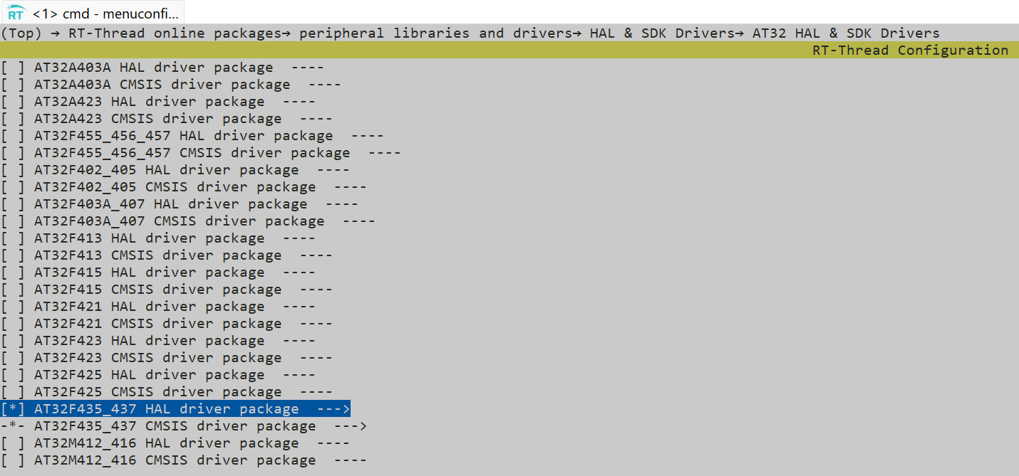
保存配置,scons --update, 下载软件包。scons --target==mdk5 生成项目文件。编译项目,有几个错误,提示找不到 fal_cfg.h文件。
因为选择了fal,还需定义内部flash分区表,文件fal_cfg.h内容如下:
#ifndef _FAL_CFG_H_
#define _FAL_CFG_H_#include <rtthread.h>
#include <board.h>#include "drv_flash.h"
#include "fal.h"#ifdef __cplusplus
extern "C" {
#endifextern const struct fal_flash_dev at32_onchip_flash;
extern struct fal_flash_dev nor_flash0;/* flash device table */
#define FAL_FLASH_DEV_TABLE                                          \
{                                                                    \&at32_onchip_flash,                                              \
}/* ====================== Partition Configuration ========================== */
#ifdef FAL_PART_HAS_TABLE_CFG/* partition table */
#define FAL_PART_TABLE                                                                       \
{                                                                                            \{FAL_PART_MAGIC_WROD,        "app",   "onchip_flash",       0,           1000 * 1024, 0}, \{FAL_PART_MAGIC_WROD,        "param", "onchip_flash",       1000 * 1024,    6 * 1024, 0}, \
}#endif /* FAL_PART_HAS_TABLE_CFG */#ifdef __cplusplus
extern "C" {
#endif#endif /* _FAL_CFG_H_ */
AT32F435RG有1M flash, 把最后boot rom/user option前面的6K作为参数存储区。
把fal_cfg.h文件存在bsp包中board/inc目录下。重新编译,完美通过!
执行 scons --dist 将配置好的项目生成独立分发版本,只要把dist目录复制出来就可以独立开发了。需要注意的是,每次运行scons --dist命令,会把dist目录里的内容清空,如有修改要做好备份!!!
完整命令为:scons --dist [--target=xxx] [--project-name="xxx"] [--project-path="xxx"]
3.修改硬件配置
由于项目用到了emac和uart1,uart3,管脚配置和at32f437-start的配置不一样,有几个地方还需要修改。
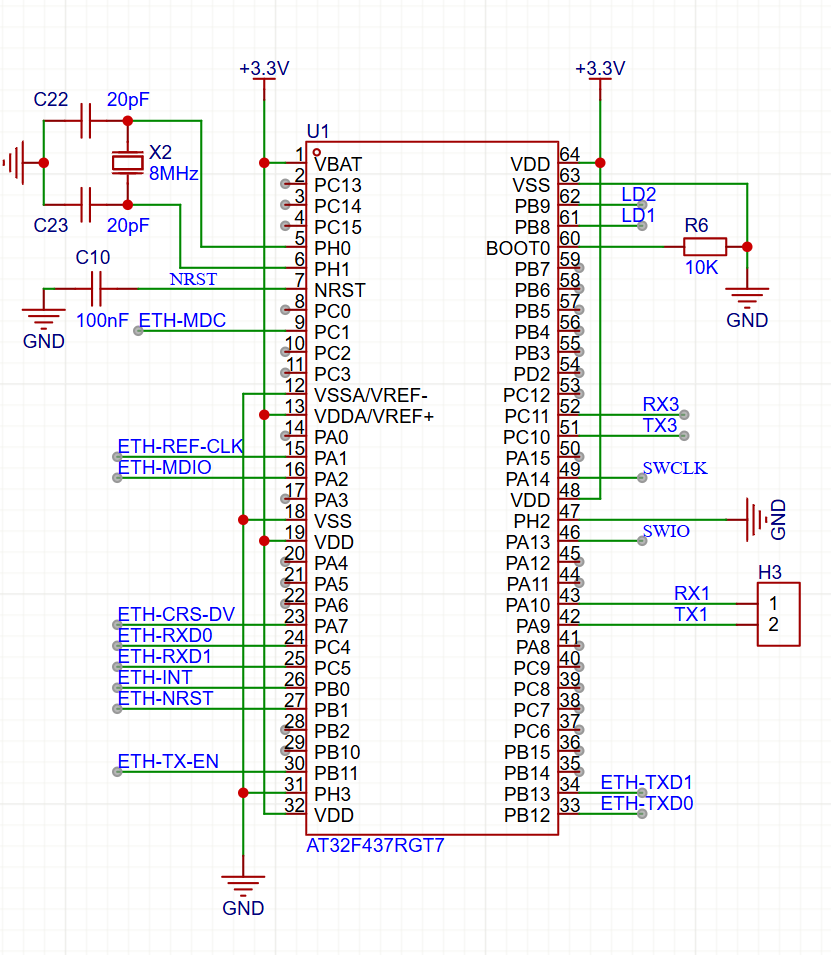
emac 采用RMII,节省资源。用到的引脚有PA1、PA2、PA7、PC1、PC4、PC5、PB11、PB12、PB13。phy芯片yt8512复位脚为PB1。
uart1使用PA9、PA10,uart3使用PC10、PC11。
除yt8512复位脚外,其它都在at32_msp.c文件中。
at32_msp.c中的修改部分。
#ifdef BSP_USING_UART3if(usart_x == USART3){crm_periph_clock_enable(CRM_USART3_PERIPH_CLOCK, TRUE);crm_periph_clock_enable(CRM_GPIOC_PERIPH_CLOCK, TRUE);gpio_init_struct.gpio_mode = GPIO_MODE_MUX;gpio_init_struct.gpio_out_type = GPIO_OUTPUT_PUSH_PULL;gpio_init_struct.gpio_pull = GPIO_PULL_NONE;gpio_init_struct.gpio_pins = GPIO_PINS_10 | GPIO_PINS_11;gpio_init(GPIOC, &gpio_init_struct);gpio_pin_mux_config(GPIOC, GPIO_PINS_SOURCE10, GPIO_MUX_7);gpio_pin_mux_config(GPIOC, GPIO_PINS_SOURCE11, GPIO_MUX_7);}
#endif#ifdef BSP_USING_EMAC
void at32_msp_emac_init(void *instance)
{gpio_init_type gpio_init_struct;crm_periph_clock_enable(CRM_GPIOA_PERIPH_CLOCK, TRUE);crm_periph_clock_enable(CRM_GPIOC_PERIPH_CLOCK, TRUE);crm_periph_clock_enable(CRM_GPIOD_PERIPH_CLOCK, TRUE);crm_periph_clock_enable(CRM_GPIOB_PERIPH_CLOCK, TRUE);//lggpio_default_para_init(&gpio_init_struct);gpio_init_struct.gpio_drive_strength = GPIO_DRIVE_STRENGTH_STRONGER;gpio_init_struct.gpio_mode = GPIO_MODE_MUX;gpio_init_struct.gpio_out_type = GPIO_OUTPUT_PUSH_PULL;gpio_init_struct.gpio_pull = GPIO_PULL_NONE;gpio_init_struct.gpio_pins = GPIO_PINS_1 | GPIO_PINS_2;gpio_init(GPIOA, &gpio_init_struct);gpio_init_struct.gpio_pins = GPIO_PINS_1;gpio_init(GPIOC, &gpio_init_struct);gpio_pin_mux_config(GPIOA, GPIO_PINS_SOURCE7, GPIO_MUX_11);gpio_pin_mux_config(GPIOC, GPIO_PINS_SOURCE4, GPIO_MUX_11);gpio_pin_mux_config(GPIOC, GPIO_PINS_SOURCE5, GPIO_MUX_11);gpio_init_struct.gpio_pins = GPIO_PINS_7;gpio_init(GPIOA, &gpio_init_struct);gpio_init_struct.gpio_pins = GPIO_PINS_4 | GPIO_PINS_5;gpio_init(GPIOC, &gpio_init_struct);gpio_init_struct.gpio_pins = GPIO_PINS_11 | GPIO_PINS_12 | GPIO_PINS_13;//lggpio_init(GPIOB, &gpio_init_struct);gpio_pin_mux_config(GPIOA, GPIO_PINS_SOURCE1, GPIO_MUX_11);gpio_pin_mux_config(GPIOA, GPIO_PINS_SOURCE2, GPIO_MUX_11);gpio_pin_mux_config(GPIOC, GPIO_PINS_SOURCE1, GPIO_MUX_11);gpio_pin_mux_config(GPIOB, GPIO_PINS_SOURCE11, GPIO_MUX_11);//lggpio_pin_mux_config(GPIOB, GPIO_PINS_SOURCE12, GPIO_MUX_11);gpio_pin_mux_config(GPIOB, GPIO_PINS_SOURCE13, GPIO_MUX_11);
}
#endif /* BSP_USING_EMAC */
phy芯片复位却PB1,需要在drv_emac.c中phy_reset()函数中修改:
static void phy_reset(void)
{gpio_init_type gpio_init_struct;#if defined (SOC_SERIES_AT32F437) || defined (SOC_SERIES_AT32F457)crm_periph_clock_enable(CRM_GPIOB_PERIPH_CLOCK, TRUE);gpio_default_para_init(&gpio_init_struct);gpio_init_struct.gpio_drive_strength = GPIO_DRIVE_STRENGTH_STRONGER;gpio_init_struct.gpio_mode = GPIO_MODE_OUTPUT;gpio_init_struct.gpio_out_type = GPIO_OUTPUT_PUSH_PULL;gpio_init_struct.gpio_pull = GPIO_PULL_NONE;gpio_init_struct.gpio_pins = GPIO_PINS_1;gpio_init(GPIOB, &gpio_init_struct);gpio_bits_reset(GPIOB, GPIO_PINS_1);rt_thread_mdelay(2);gpio_bits_set(GPIOB, GPIO_PINS_1);
#endif
#if defined (SOC_SERIES_AT32F407)crm_periph_clock_enable(CRM_GPIOC_PERIPH_CLOCK, TRUE);gpio_default_para_init(&gpio_init_struct);gpio_init_struct.gpio_drive_strength = GPIO_DRIVE_STRENGTH_STRONGER;gpio_init_struct.gpio_mode = GPIO_MODE_OUTPUT;gpio_init_struct.gpio_out_type = GPIO_OUTPUT_PUSH_PULL;gpio_init_struct.gpio_pull = GPIO_PULL_NONE;gpio_init_struct.gpio_pins = GPIO_PINS_8;gpio_init(GPIOC, &gpio_init_struct);gpio_bits_reset(GPIOC, GPIO_PINS_8);rt_thread_mdelay(2);gpio_bits_set(GPIOC, GPIO_PINS_8);
#endifrt_thread_mdelay(2000);
}
最后还要在项目属性页(Device和C/C++)中把单片机型号改成AT32F437RG.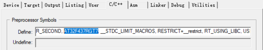
4. 遇到的问题
程序跑起来后,发现网络有问题。phy_linkchange函数没被调用,导致网络不能用。经分析,是phy_monitor_thread_entry函数中的rt_thread_mdelay()导致线程挂起后,时间到了也没被唤醒,后续代码就没有执行到。
static void phy_monitor_thread_entry(void *parameter)
{uint8_t detected_count = 0;while(phy_addr == 0xFF){/* phy search */rt_uint32_t i, temp;for (i = 0; i <= 0x1F; i++){emac_phy_register_read(i, PHY_BASIC_STATUS_REG, (uint16_t *)&temp);if (temp != 0xFFFF && temp != 0x00){phy_addr = i;break;}}detected_count++;//rt_thread_mdelay(1000);if (detected_count > 10){LOG_E("No PHY device was detected, please check hardware!");}}LOG_D("Found a phy, address:0x%02X", phy_addr);/* reset phy */LOG_D("RESET PHY!");emac_phy_register_write(phy_addr, PHY_BASIC_CONTROL_REG, PHY_RESET_MASK);//rt_thread_mdelay(2000);emac_phy_register_write(phy_addr, PHY_BASIC_CONTROL_REG, PHY_AUTO_NEGOTIATION_MASK);phy_linkchange();
#ifdef PHY_USING_INTERRUPT_MODE/* configuration intterrupt pin */rt_pin_mode(PHY_INT_PIN, PIN_MODE_INPUT_PULLUP);rt_pin_attach_irq(PHY_INT_PIN, PIN_IRQ_MODE_FALLING, emac_phy_isr, (void *)"callbackargs");rt_pin_irq_enable(PHY_INT_PIN, PIN_IRQ_ENABLE);/* enable phy interrupt */emac_phy_register_write(phy_addr, PHY_INTERRUPT_MASK_REG, PHY_INT_MASK);
#if defined(PHY_INTERRUPT_CTRL_REG)emac_phy_register_write(phy_addr, PHY_INTERRUPT_CTRL_REG, PHY_INTERRUPT_EN);
#endif
#else /* PHY_USING_INTERRUPT_MODE */at32_emac_device.poll_link_timer = rt_timer_create("phylnk", (void (*)(void*))phy_linkchange,NULL, RT_TICK_PER_SECOND, RT_TIMER_FLAG_PERIODIC);if (!at32_emac_device.poll_link_timer || rt_timer_start(at32_emac_device.poll_link_timer) != RT_EOK){LOG_E("Start link change detection timer failed");}
#endif /* PHY_USING_INTERRUPT_MODE */
}
把两个rt_thread_mdelay调用注释掉,正常。延时估计是为兼容不同的Phy芯片,对于YT8512不延时没有问题。
至于为什么delay会让线程没法唤醒,还没有仔细分析!!!可能细节还在其它地方。