【星闪】Hi2821 | UART通用异步收发器 + 串口中断收发例程
1. 简介
UART(Universal Asynchronous Receiver/Transmitter),通用异步收发器,是一种串行、异步、全双工的通信协议,用于设备间的数据传输。一般串口通信的数据包如下图:
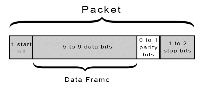
通常由起始位、数据位、校检位和停止位组成。
- 起始位:1位,用于标志数据包的开始;
- 数据位:5-9位,包含要发送的数据;
- 校检位:0-1位,可选无校检、奇校检和偶校检;
- 停止位:1-2位,标志数据包的结束。
在配置串口时有一个很重要的参数——波特率,它定义接口收发数据的速率。因为UART是异步通讯,没有时钟线,所以通讯双方需要保持同样的速率才能正常通信。波特率表示的是每秒传输的比特数,常见的有9600bps和115200bps。
2. 硬件配置
Hi2821一共有3个UART——UART0(UART_L0)、UART1(UART_H0)、UART2(UART_L1)。其中UART0是默认作为系统debug和程序烧录的接口,其余的用户都可配置。
UART支持流控工作模式,并支持配置RTS。内置 64×8 的 TX FIFO 以及 RX FIFO。支持接收 FIFO 中断、发送 FIFO 中断、接收超时中断、错误中断等中断屏蔽与响应。
3. 例程
3.1 Kconfig
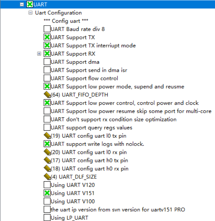
SDK是默认开启对UART的编译的,仅需要使能串口发送中断即可。
3.2 代码
#include "soc_osal.h"
#include "app_init.h"
#include "common_def.h"
#include "securec.h"
#include "pinctrl.h"
#include "gpio.h"
#include "uart.h"#include <string.h>
#include <stdint.h>#define UART_TX_GPIO 17
#define UART_RX_GPIO 18#define UART_BUS UART_BUS_1
#define UART_BUF_LEN 64static uint8_t rx_buf[UART_BUF_LEN] = {0};static uart_buffer_config_t buf_conf = {.rx_buffer = rx_buf,.rx_buffer_size = UART_BUF_LEN
};static const char* tx_msg = "Hello from hi2821";static void uart_read_int_handler(const void *buffer, uint16_t length, bool error)
{unused(error);if (buffer == NULL || length == 0) {osal_printk("buffer empty or receive error\r\n");return;}osal_printk("receive %d bytes of data: %s\r\n", length, (const char*) buffer);
}static void uart_write_int_handler(const void *buffer, uint32_t length, const void *params)
{unused(params);osal_printk("write %d bytes of data: %s\r\n", length, (const char*) buffer);
}void app_main(void *unused)
{UNUSED(unused);/* 初始化GPIO */uapi_pin_set_ie(UART_RX_GPIO, PIN_IE_1);uapi_pin_set_mode(UART_TX_GPIO, HAL_PIO_UART_H0_TXD);uapi_pin_set_mode(UART_RX_GPIO, HAL_PIO_UART_H0_RXD);/* 初始化UART */uart_attr_t attr = {.baud_rate = 115200,  // 波特率.data_bits = UART_DATA_BIT_8,  // 8位数据位.stop_bits = UART_STOP_BIT_1,  // 1位停止位.parity = UART_PARITY_NONE,  // 无校检.flow_ctrl = UART_FLOW_CTRL_NONE  // 无流控};uart_pin_config_t pin_config = {.tx_pin = UART_TX_GPIO,.rx_pin = UART_RX_GPIO,.cts_pin = PIN_NONE,.rts_pin = PIN_NONE};uapi_uart_deinit(UART_BUS);uapi_uart_init(UART_BUS, &pin_config, &attr, NULL, &buf_conf);uapi_uart_register_rx_callback(UART_BUS, UART_RX_CONDITION_FULL_OR_SUFFICIENT_DATA_OR_IDLE, 1, uart_read_int_handler);while (1) {/* 串口发送 */errcode_t ret = uapi_uart_write_int(UART_BUS, (const uint8_t*) tx_msg, strlen(tx_msg), NULL, uart_write_int_handler);if (ret == ERRCODE_SUCC) {osal_printk("send message succ\r\n");} else {osal_printk("send message failed, err: %08X\r\n", ret);}osal_msleep(2000);}
}
1. 初始化 Pinctrl。
例程中使用的是 UART1,对应 UART_H0,调 uapi_pin_set_mode 函数使能管脚的复用。如果 Kconfig 里面使能了 CONFIG_PINCTRL_SUPPORT_IE,那么还需要调 uapi_pin_set_ie 使能串口接收管脚的输入功能。
2. 初始化 UART。
串口的初始化(中断模式)需要三个结构体——uart_attr_t、uart_pin_config_t 和 uart_buffer_config_t,定义如下:
typedef struct uart_attr {uint32_t baud_rate;                 /*!< @if Eng UART baud rate@else UART波特率 @endif */uint8_t data_bits;                  /*!< @if Eng UART data bits, For details see .@else   UART数据位,参考 @ref uart_data_bit_t @endif */uint8_t stop_bits;                  /*!< @if Eng UART stop bits, For details see .@else   UART数据位,参考 @ref uart_stop_bit_t @endif */uint8_t parity;                     /*!< @if Eng UART parity, For details see .@else   UART 奇偶校验位,参考 @ref uart_parity_t @endif */uint8_t flow_ctrl;                  /*!< @if Eng UART flow control, For details see @ref uart_flow_ctrl_t.@else   UART 流控,参考 @ref uart_flow_ctrl_t @endif */
} hal_uart_attr_t;typedef struct {pin_t tx_pin;                   /*!< @if Eng Transmission PIN.@else   发送引脚 @endif */pin_t rx_pin;                   /*!< @if Eng Reception PIN.@else   接收引脚 @endif */pin_t cts_pin;                  /*!< @if Eng Clear to send PIN.@else   发送就绪引脚 @endif */pin_t rts_pin;                  /*!< @if Eng Request to send PIN to use.@else   接收就绪引脚 @endif */
} hal_uart_pin_config_t;typedef struct uart_buffer_config {void *rx_buffer;            /*!< @if Eng Reception buffer pointer.@else   接收数据的buffer指针  @endif */size_t rx_buffer_size;      /*!< @if Eng Reception buffer size in bytes.@else   接收Buffer的长度  @endif */
} uart_buffer_config_t;
uart_attr_t 结构体用于配置通讯的参数,例程中是配置为常见的 115200bps,8位数据位,无校检,1位停止位。
uart_pin_config_t 结构体用于配置通讯管脚,例程中没有用到流控,所以只需设置发送和接收管脚即可,我这里设置的是 IO17 和 IO18。
uart_buffer_config_t 结构体用于设置接收缓冲区。
在初始化 UART 前建议调 uapi_uart_deinit 函数反初始化一下,然后再调 uapi_uart_init 函数初始化 UART。
对于中断模式下的数据接收,需调 uapi_uart_register_rx_callback 函数去注册接收回调。参数一为 UART 的总线号;参数二为中断回调的触发条件,有以下可选项:
typedef enum uart_rx_condition {/** @if Eng  A call-back will be made if the RX data pauses or there is no more RX buffer space. \n*           So data is no longer being accepted. When registering this condition, a back-log of.*  @else    如果数据接收暂停,或者接收缓存已经满了,就触发数据接收回调,\n*           在接收回调处理过程中接收到的UART数据,会直接丢弃。*  @endif */UART_RX_CONDITION_FULL_OR_IDLE = (UART_RX_CONDITION_MASK_FULL | UART_RX_CONDITION_MASK_IDLE),/** @if Eng A call-back will be made as soon as possible after the specified amount of data is*          received or there is no more RX buffer space. \n*          So data is no longer being accepted. More than the requested data may be*          provided to the call-back if there was a back-log of received data.*  @else   如果接收缓存已满,或者接收的数据量到达指定的数据长度,就触发数据接收回调,\n*          在接收回调处理过程中接收到的UART数据,会直接丢弃。*          如果存在接收数据的积压数据,则可以向回调提供超过请求的数据。 @endif */UART_RX_CONDITION_FULL_OR_SUFFICIENT_DATA = (UART_RX_CONDITION_MASK_FULL | UART_RX_CONDITION_MASK_SUFFICIENT_DATA),/** @if Eng A call-back will be made if the RX data buffer is full or*          the specified number of bytes has been received or there is a pause. \n*          So data is no longer being accepted.*  @else   如果接收缓存已满,或者接收的数据量到达指定的数据长度,或者接收数据暂停,就触发数据接收回调,\n*          在接收回调处理过程中接收到的UART数据,会直接丢弃。 @endif */UART_RX_CONDITION_FULL_OR_SUFFICIENT_DATA_OR_IDLE = (UART_RX_CONDITION_MASK_FULL |UART_RX_CONDITION_MASK_SUFFICIENT_DATA |UART_RX_CONDITION_MASK_IDLE)
} uart_rx_condition_t;
参数三为中断触发的缓冲区数据阈值,即当接收的数据量达到该阈值才会触发回调函数,函数执行完后缓冲区就会清空重新计数;参数四就是回调函数的指针,回调中例程只是简单地打印了接收到的数据。
3. 主函数。
任务循环里面调用 uapi_uart_write_int 函数定期向串口发送数据;参数一为 UART 总线号;参数二为要发送的数据;参数三为数据的长度;参数四为回调函数的用户参数;参数五为回调函数指针。回调函数里面也是简单地打印发送的数据。
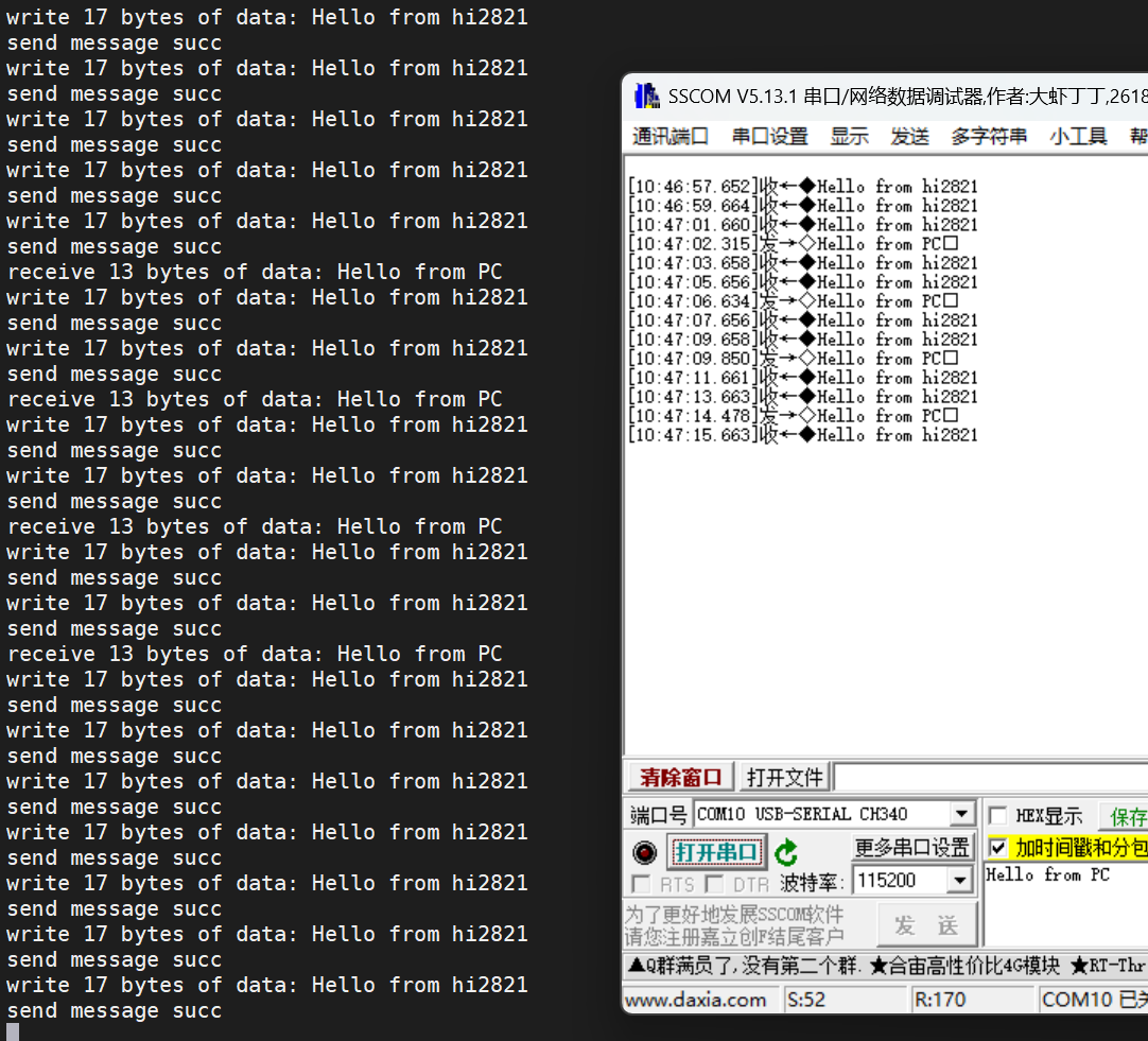
3.3 测试
测试时需额外准备一个串口调试助手,接线按照发送管脚和接收管脚两两连接的线序,同时两者间的地线也要相连。
固件烧录后能看到串口助手不断打印单片机串口发送过来的数据,串口助手中发送数据到单片机,单片机的log同样能打印发送过来的数据。