【华为】现场配置OSPF
原创:厦门微思网络
实验目的
1、了解OSPF的运行原理
2、掌握OSPF的配置方法
实验拓扑
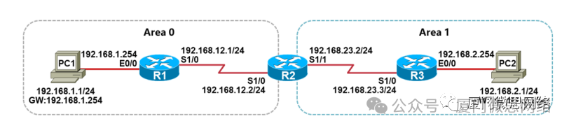
实验需求
1、根据实验拓扑图,完成设备的基本配置;
2、分别在R1、R2、R3上创建Loopback0接口,IP地址分别是1.1.1.1/32、2.2.2.2/32、3.3.3.3/32,Loopback0地址作为OSPF的Router-ID;
3、根据实验拓扑图的区域划分,在R1、R2、R3上配置OSPF,使得全网路由可达。
实验拓扑
步骤1:设备的基本配置
配置PC1:
VPCS> set pcname PC1   //设置主机名
PC1> ip 192.168.1.1/24 192.168.1.254    //设置IP地址与网关
配置PC2:
VPCS> set pcname PC2
PC2> ip 192.168.2.1/24 192.168.2.254
配置R1:
Router>enable
Router#configure terminal
Router(config)#hostname R1
R1(config)#no ip domain-lookup
R1(config)#line console 0
R1(config-line)#exec-timeout 0 0
R1(config-line)#logging synchronous
R1(config-line)#exit
R1(config)#interface loopback0
R1(config-if)#ip address 1.1.1.1 255.255.255.255
R1(config-if)#exitR1(config)#interface ethernet0/0
R1(config-if)#ip address 192.168.1.254 255.255.255.0
R1(config-if)#no shutdown
R1(config-if)#exit
R1(config)#interface serial1/0
R1(config-if)#ip address 192.168.12.1 255.255.255.0
R1(config-if)#no shutdown
R1(config-if)#endR1#
配置R2:
Router>enable
Router#configure terminal
Router(config)#hostname R2
R2(config)#no ip domain-lookup
R2(config)#line console 0
R2(config-line)#exec-timeout 0 0
R2(config-line)#logging synchronous
R2(config-line)#exit
R2(config)#interface loopback0
R2(config-if)#ip address 2.2.2.2 255.255.255.255
R2(config-if)#exit
R2(config)#interface serial1/0
R2(config-if)#ip address 192.168.12.2 255.255.255.0
R2(config-if)#no shutdown
R2(config-if)#exit
R2(config)#interface serial1/1
R2(config-if)#ip address 192.168.23.2 255.255.255.0
R2(config-if)#no shutdown
R2(config-if)#endR2#
配置R3:
Router>enable
Router#configure terminal
Router(config)#hostname R3
R3(config)#no ip domain-lookup
R3(config)#line console 0
R3(config-line)#exec-timeout 0 0
R3(config-line)#logging synchronous
R3(config-line)#exit
R3(config)#interface loopback0
R3(config-if)#ip address 3.3.3.3 255.255.255.255
R3(config-if)#exit
R3(config)#interface ethernet0/0
R3(config-if)#ip address 192.168.2.254 255.255.255.0
R3(config-if)#no shutdown
R3(config-if)#exit
R3(config)#interface serial1/0
R3(config-if)#ip address 192.168.23.3 255.255.255.0
R3(config-if)#no shutdown
R3(config-if)#endR3#
步骤2:检查设备接口状态
检查PC1:
PC1> show ip
NAME        : PC1[1]
IP/MASK     : 192.168.1.1/24
GATEWAY     : 192.168.1.254
DNS         :
MAC         : 00:50:79:66:68:04
LPORT       : 20000
RHOST:PORT  : 127.0.0.1:30000
MTU         : 1500
检查R1:
R1#show ip interface brief
Interface                  IP-Address      OK? Method Status                Protocol
Ethernet0/0                192.168.1.254   YES manual up                    up
Ethernet0/1                unassigned      YES unset  administratively down down
Ethernet0/2                unassigned      YES unset  administratively down down
Ethernet0/3                unassigned      YES unset  administratively down down
Serial1/0                  192.168.12.1    YES manual up                    up
Serial1/1                  unassigned      YES unset  administratively down down
Serial1/2                  unassigned      YES unset  administratively down down
Serial1/3                  unassigned      YES unset  administratively down down
Loopback0                  1.1.1.1         YES manual up                    up
检查R2:
R2#show ip interface brief
Interface                  IP-Address      OK? Method Status                ProtocolEthernet0/0                unassigned      YES unset  administratively down down
Ethernet0/1                unassigned      YES unset  administratively down down
Ethernet0/2                unassigned      YES unset  administratively down down
Ethernet0/3                unassigned      YES unset  administratively down down
Serial1/0                  192.168.12.2    YES manual up                    up
Serial1/1                  192.168.23.2    YES manual up                    up
Serial1/2                  unassigned      YES unset  administratively down down
Serial1/3                  unassigned      YES unset  administratively down down
Loopback0                  2.2.2.2         YES manual up                    up
检查R3:
R3#show ip interface brief
Interface                  IP-Address      OK? Method Status                Protocol
Ethernet0/0                192.168.2.254   YES manual up                    up
Ethernet0/1                unassigned      YES unset  administratively down down
Ethernet0/2                unassigned      YES unset  administratively down down
Ethernet0/3                unassigned      YES unset  administratively down down
Serial1/0                  192.168.23.3    YES manual up                    up
Serial1/1                  unassigned      YES unset  administratively down down
Serial1/2                  unassigned      YES unset  administratively down down
Serial1/3                  unassigned      YES unset  administratively down down
Loopback0                  3.3.3.3         YES manual up                    up
检查PC2:
PC2> show ip
NAME        : PC2[1]
IP/MASK     : 192.168.2.1/24
GATEWAY     : 192.168.2.254
DNS         :
MAC         : 00:50:79:66:68:05
LPORT       : 20000
RHOST:PORT  : 127.0.0.1:30000
MTU         : 1500
步骤3:测试直连网络的连通性
测试PC1跟网关的网络连通性:
PC1> ping 192.168.1.254
84 bytes from 192.168.1.254 icmp_seq=1 ttl=255 time=0.359 ms
84 bytes from 192.168.1.254 icmp_seq=2 ttl=255 time=0.459 ms
84 bytes from 192.168.1.254 icmp_seq=3 ttl=255 time=0.463 ms
84 bytes from 192.168.1.254 icmp_seq=4 ttl=255 time=0.403 ms
84 bytes from 192.168.1.254 icmp_seq=5 ttl=255 time=0.417 ms
测试R1跟R2之间的网络连通性:
R1#ping 192.168.12.2
Type escape sequence to abort.
Sending 5, 100-byte ICMP Echos to 192.168.12.2, timeout is 2 seconds:
!!!!!
Success rate is 100 percent (5/5), round-trip min/avg/max = 8/9/10 ms
测试R2跟R3之间的网络连通性:
R2#ping 192.168.23.3
Type escape sequence to abort.
Sending 5, 100-byte ICMP Echos to 192.168.23.3, timeout is 2 seconds:
!!!!!
Success rate is 100 percent (5/5), round-trip min/avg/max = 9/9/11 ms
测试PC2跟网关的网络连通性:
PC2> ping 192.168.2.254
84 bytes from 192.168.2.254 icmp_seq=1 ttl=255 time=0.469 ms
84 bytes from 192.168.2.254 icmp_seq=2 ttl=255 time=0.484 ms
84 bytes from 192.168.2.254 icmp_seq=3 ttl=255 time=0.518 ms
84 bytes from 192.168.2.254 icmp_seq=4 ttl=255 time=0.400 ms
84 ytes from 192.168.2.254 icmp_seq=5 ttl=255 time=0.405 ms
步骤4:配置OSPF
配置R1:
R1(config)#router ospf 1
R1(config-router)#router-id 1.1.1.1
R1(config-router)#network 192.168.1.0 0.0.0.255 area 0
R1(config-router)#network 192.168.12.0 0.0.0.255 area 0
R1(config-router)#endR1#
配置R2:
R2(config)#router ospf 1
R2(config-router)#router-id 2.2.2.2
R2(config-router)#network 192.168.12.0 0.0.0.255 area 0
R2(config-router)#network 192.168.23.0 0.0.0.255 area 1
R2(config-router)#endR2#
配置R3:
R3(config)#router ospf 1
R3(config-router)#router-id 3.3.3.3
R3(config-router)#network 192.168.23.0 0.0.0.255 area 1
R3(config-router)#network 192.168.2.0 0.0.0.255 area 1
R3(config-router)#endR3#
实验拓扑
步骤1:检查OSPF邻居
检查R1:
R1#show ip ospf neighbor
Neighbor ID     Pri   State           Dead Time   Address         Interface
2.2.2.2           0   FULL/  -        00:00:31    192.168.12.2    Serial1/0
Full是完全邻接状态,是正常的状态。
检查R2:
R2#show ip ospf neighbor
Neighbor ID     Pri   State           Dead Time   Address         Interface
1.1.1.1           0   FULL/  -        00:00:31    192.168.12.1    Serial1/0
3.3.3.3           0   FULL/  -        00:00:39    192.168.23.3    Serial1/1
检查R3:
R3#show ip ospf neighbor
Neighbor ID     Pri   State           Dead Time   Address         Interface
2.2.2.2           0   FULL/  -        00:00:33    192.168.23.2    Serial1/0
步骤2:检查OSPF路由
检查R1:
R1#show ip route
Codes: L - local, C - connected, S - static, R - RIP, M - mobile, B - BGPD - EIGRP, EX - EIGRP external, O - OSPF, IA - OSPF inter areaN1 - OSPF NSSA external type 1, N2 - OSPF NSSA external type 2E1 - OSPF external type 1, E2 - OSPF external type 2i - IS-IS, su - IS-IS summary, L1 - IS-IS level-1, L2 - IS-IS level-2ia - IS-IS inter area, * - candidate default, U - per-user static routeo - ODR, P - periodic downloaded static route, H - NHRP, l - LISPa - application route+ - replicated route, % - next hop override, p - overrides from PfR
Gateway of last resort is not set1.0.0.0/32 is subnetted, 1 subnets
C        1.1.1.1 is directly connected, Loopback0192.168.1.0/24 is variably subnetted, 2 subnets, 2 masks
C        192.168.1.0/24 is directly connected, Ethernet0/0
L        192.168.1.254/32 is directly connected, Ethernet0/0
O IA   192.168.2.0/24 [110/138] via 192.168.12.2, 00:04:48, Serial1/0192.168.12.0/24 is variably subnetted, 2 subnets, 2 masks
C        192.168.12.0/24 is directly connected, Serial1/0
L        192.168.12.1/32 is directly connected, Serial1/0
O IA   192.168.23.0/24 [110/128] via 192.168.12.2, 00:06:10, Serial1/0
R1有两条O IA的路由,O IA表示OSPF区域间的路由;
因为R1所有接口都是属于Area 0,192.168.2.0/24和192.168.23.0/24都是属于Area 1,所以通过R2跨区域传递给R1之后,就形成了O IA路由。
检查R2:
R2#show ip route
Codes: L - local, C - connected, S - static, R - RIP, M - mobile, B - BGPD - EIGRP, EX - EIGRP external, O - OSPF, IA - OSPF inter area       N1 - OSPF NSSA external type 1, N2 - OSPF NSSA external type 2       E1 - OSPF external type 1, E2 - OSPF external type 2i - IS-IS, su - IS-IS summary, L1 - IS-IS level-1, L2 - IS-IS level-2ia - IS-IS inter area, * - candidate default, U - per-user static routeo - ODR, P - periodic downloaded static route, H - NHRP, l - LISPa - application route+ - replicated route, % - next hop override, p - overrides from PfR
Gateway of last resort is not set2.0.0.0/32 is subnetted, 1 subnets
C        2.2.2.2 is directly connected, Loopback0
O     192.168.1.0/24 [110/74] via 192.168.12.1, 00:09:55, Serial1/0
O     192.168.2.0/24 [110/74] via 192.168.23.3, 00:08:24, Serial1/1192.168.12.0/24 is variably subnetted, 2 subnets, 2 masks
C        192.168.12.0/24 is directly connected, Serial1/0
L        192.168.12.2/32 is directly connected, Serial1/0192.168.23.0/24 is variably subnetted, 2 subnets, 2 masks
C        192.168.23.0/24 is directly connected, Serial1/1
L        192.168.23.2/32 is directly connected, Serial1/1
因为R1既有接口属于Area 0,也有接口属于Area 1;
所以R1的路由表看到的都是O路由,O表示OSPF区域内的路由。